WIZM-LDR
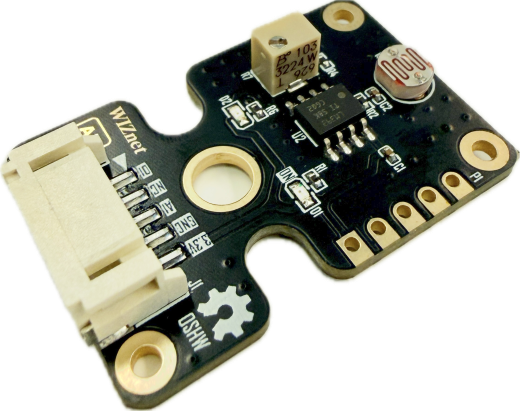
WIZM-LDR is a light detection sensor module featuring an onboard photoresistor (LDR) and an LM393DR dual voltage comparator. It provides dual output modes: an analog output (AI) for continuous ambient light intensity measurement, and a digital output (DI) for threshold-based light level detection adjustable via an onboard potentiometer.
 Buy now
The WIZM-LDR is an ambient light sensing board integrating a sensitive light-dependent resistor (LDR) and an LM393DR comparator circuit. It allows microcontrollers to easily monitor environmental lighting conditions either by reading variable voltage proportional to light exposure via its analog pin (AI) or by triggering events using its digital switching output (DI). With dual 5-pin headers (standard 2.54mm through-hole header and a right-angle keyed connector), onboard status LEDs, and a sensitivity adjustment trimmer, it is ideal for smart home lighting, daylight sensing, and IoT monitoring systems.
Features
Dual Output Modes:
Analog Output (AI): Continuous voltage readout reflecting ambient light intensity.
Digital Output (DI): Logic output switching based on user-configured light threshold.
Onboard Comparator: Powered by an LM393DR precision dual voltage comparator.
Sensitivity Adjustment: Integrated potentiometer trimmer allows fine-tuning of the digital switching trigger level.
Status Indicator LEDs: Onboard power indicator and digital output status LED.
Dual Connection Options: Supports standard 2.54mm pitch pin headers (P1) alongside a keyed horizontal lock connector (J1).
Standardized Mounting: Four corner mounting holes plus a center pass-through hole for panel and chassis installation.
Specifications
Parameter |
Value |
|---|---|
Model (P/N) |
WIZM-LDR |
Function |
Light Photoresistor |
Main IC |
LM393DR |
Interface (I/F) |
Analog / Digital (AO / DI) |
Revision |
1.0 |
Operating Voltage (VCC) |
3.3V DC |
Connector Pitch |
Standard 2.54mm (P1) / Keyed Horizontal (J1) |
Pin Count |
5 Pins ( |
Pinout & Hardware Overview
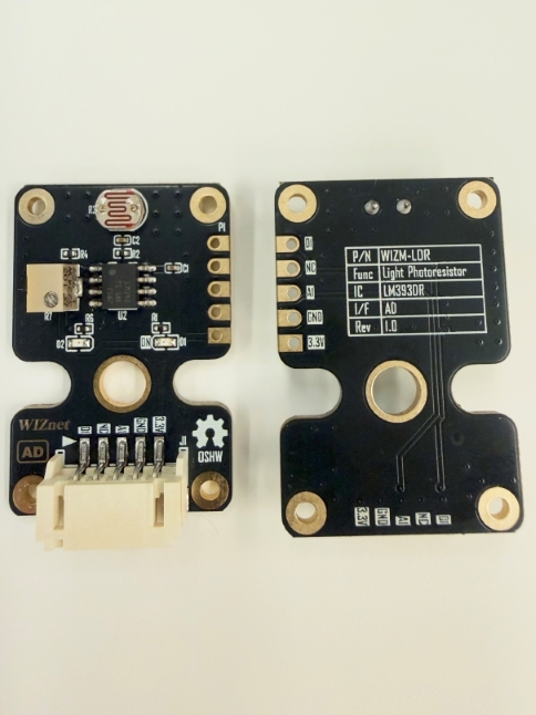
The module provides two parallel pin interfaces: a standard 5-pin 2.54mm pitch breakout (P1) and a 5-pin horizontal keyed connector (J1).
Pin |
Type |
Description |
|---|---|---|
D1 |
Output |
Digital Output (threshold-triggered logic signal via LM393DR) |
NC |
- |
Not Connected / Reserved |
A1 |
Output |
Analog Output (variable voltage relative to ambient light level) |
GND |
Power |
Ground supply reference |
3.3V |
Power |
3.3V DC power supply input |
Top View & Bottom View
Platforms Supported
MicroPython |
|---|
|
Getting Started
Materials Required (excluding sensor module)
W55MH32L-Application-KIT
5-pin female-to-female JST PH-style cable
USB Type-C cable
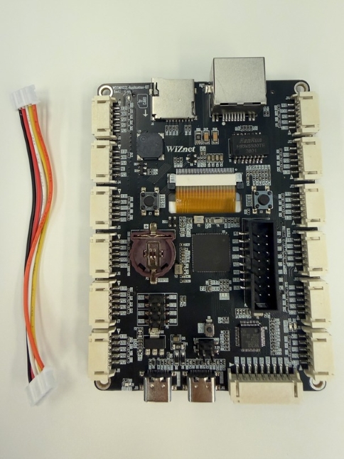
Hardware Connection
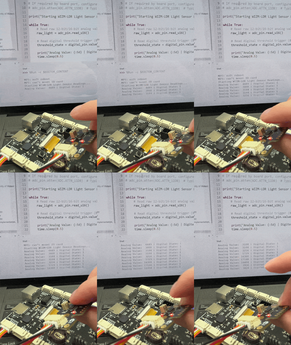
Connect the WIZM-LDR to an ADC-enabled connector (e.g., J3) on the W55MH32L-Application-KIT using the 5-pin JST cable.
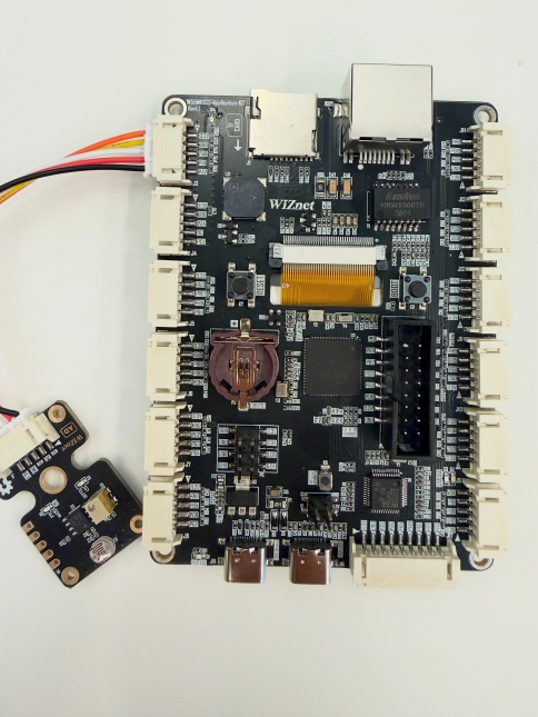
Then use a USB Type‑C cable to connect the WIZ‑LINK Port on the W55MH32L‑Application-KIT board to your PC
Sample Code Demo
Software
We will be using Thonny IDE to run the code.
Open Thonny IDE on your PC.
Select the correct COM port for your board.
Set the interpreter to MicroPython (generic).
Refer to the WIZnet documentation page for detailed carrier board setup.
MicroPython
from machine import ADC, Pin
import time

# Update pin labels to match your carrier board's connector routing
# AI is connected to an ADC-capable pin; DI is connected to a standard GPIO pin
adc_pin = ADC(Pin("PA0"))  # Analog Light Input (AI)
digital_pin = Pin("PB0", Pin.IN)  # Digital Trigger Input (DI)

print("Starting WIZM-LDR Light Sensor Readings...")

while True:
    # Read raw 12-bit/16-bit analog value
    raw_light = adc_pin.read_u16()

    # Read digital threshold trigger (0 or 1)
    threshold_state = digital_pin.value()

    print("Analog Value: {:5d} | Digital State: {}".format(raw_light, threshold_state))
    time.sleep(0.5)