MicroPython Reference Script
In this page, we will show all network and peripheral MicroPython script with simple setup.

WIZnet5K Networking
See network.WIZNET5K and socket.
- Basic Setup for Networking:
Connect the board and PC with an Ethernet cable.
Set the IP address of the board and PC in the same IP segment.
Network Configuration
Script: GitHub
YouTube Tutorial: Watch Network Configuration demo video
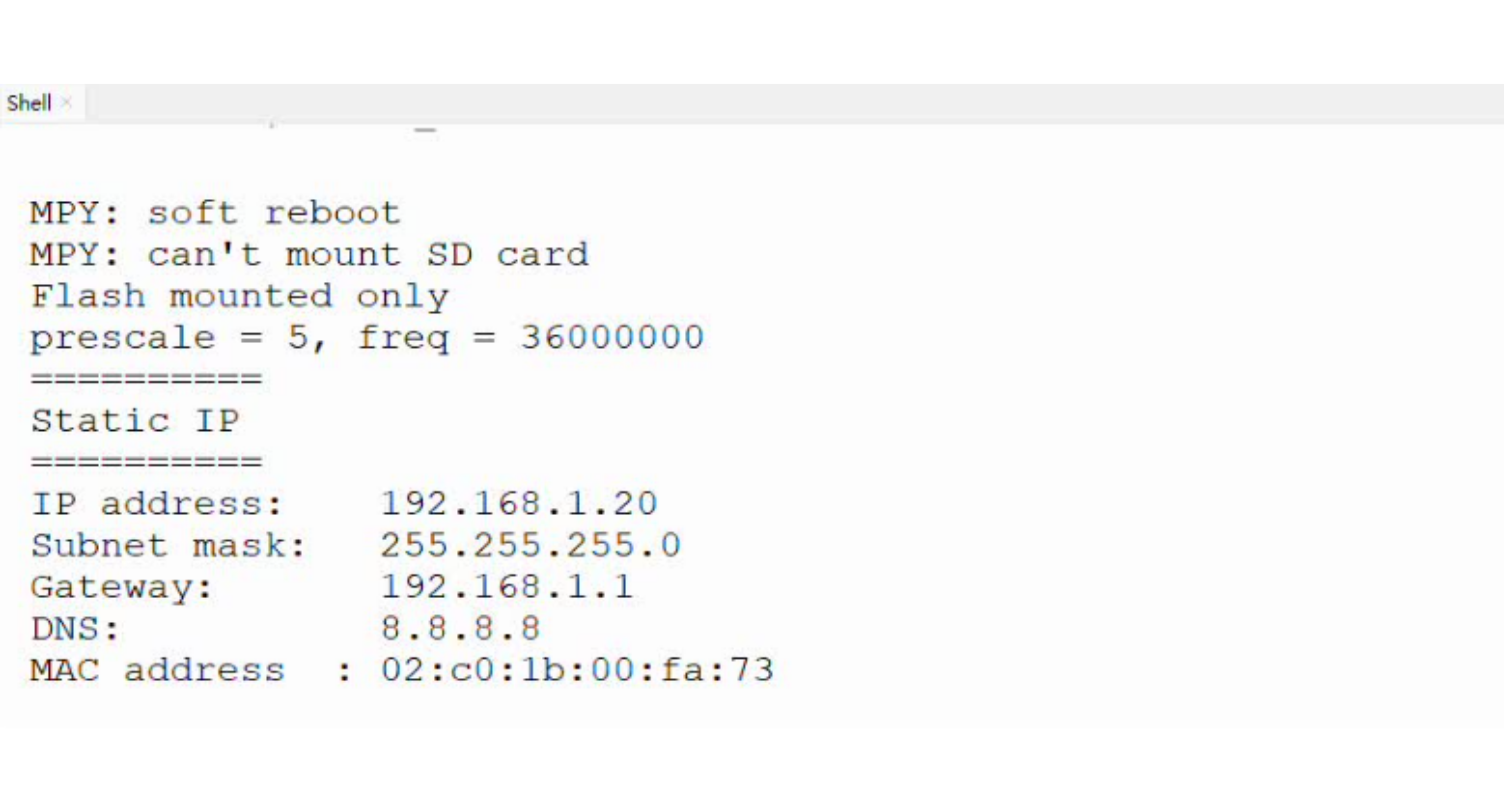
Static IP
- Results:
It shows the IP address details set inside the script.
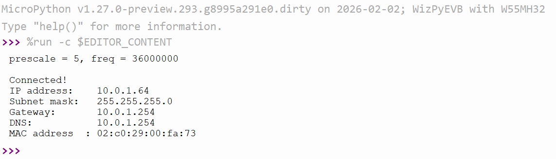
DHCP
- Results:
It shows the IP address details provided by the DHCP server or router.
TCP
YouTube Tutorial: Watch TCP Client & Server demo video
TCP Server
Script: GitHub
- Setup:
Set your PC’s IP to
192.168.1.100.Run the script – board gets IP
192.168.1.20and waits for one client on port5000.Connect a TCP client (e.g.,
WIZnet Socket Tester) to192.168.1.20:5000and send any message.
- Results:
The board replies with
Echo: <your message>.Send
exitto close the connection; the script ends.Run the script again to accept a new client.
TCP Client
Script: GitHub
- Setup:
Set your PC’s IP to
192.168.1.100and run a TCP server on port5000(e.g.,WIZnet Socket Tester).Run the script – board gets IP
192.168.1.21and connects to server at192.168.1.20:5000.
- Results:
The board sends
Hello,World,Test, thenexit.For each message except
exit, it prints the server’s echo reply.After sending
exit, the socket closes and the script ends.

UDP
YouTube Tutorial: Watch UDP Client & Server demo video
UDP Server
Script: GitHub
- Setup:
Set the board’s IP to
169.254.100.50.Run the script – it binds to port
5000and waits for incoming UDP packets.Send messages from any UDP client.
- Results:
The server prints every received message.
When the server receives the word
exit, it closes the socket and stops.Run the script again to restart listening.
UDP Client
Script: GitHub
- Setup:
Set the board’s IP to
169.254.100.50(or modify the script as needed).Ensure the target server IP (e.g.,
169.254.219.97) is reachable on port5000.Run the script – it binds to port
5000.
- Results:
Type any message in the MicroPython shell; the client sends it to the server.
The client prints
Sent: <your message>(no reply expected).Type
exitto close the socket and end the script.
DNS (Domain Name System)
Script: GitHub
YouTube Tutorial: Watch DNS demo video
- Setups:
Connect the board and your PC to the same network using Ethernet cables.
Set your PC’s IP address to match the board’s subnet (e.g., 10.0.1.x).
Run the script – it configures the board with static IP
10.0.1.50and DNS server8.8.8.8.
- Results:
The script resolves
docs.w5500.comusing Google’s DNS server.It prints the corresponding IP address on the MicroPython shell.
You can verify the result using any DNS lookup tool (e.g., Google Admin Toolbox Dig).
NTP (Network Time Protocol)
See machine.RTC
Script: GitHub
tm1637 Library: GitHub.
ntptime Library: GitHub.
YouTube Tutorial: Watch NTP demo video
- Setups:
Connect a TM1637 7‑segment display module: CLK → PG7, DIO → PG8, VCC → 5V, GND → GND.
Connect the board and your PC to the same network (Ethernet).
Adjust the static IP configuration in the script to match your network (example uses
10.0.1.50/24).
- Results:
The display first shows the wrong time (10:30) for 5 seconds.
The board then fetches the real UTC time from an NTP server and updates the internal RTC.
After sync, the display shows the correct current time (hours:minutes) and continues updating every 0.5 seconds.
The MicroPython shell also prints the time in
HH:MM:SSformat.
HTTP Web Server
Script: GitHub
YouTube Tutorial: Watch HTTP server demo
- Setups:
Connect an RGB LED (common cathode) to pins PA6 (red), PB9 (green), PA0 (blue) with appropriate resistors.
Connect the board and your PC to the same Ethernet network.
Run the script – it assigns static IP
169.254.100.20and listens on port8080.
- Results:
Open a web browser and go to
http://169.254.100.20:8080.Three range sliders appear (red, green, blue). Drag any slider.
The RGB LED changes colour instantly without page reload (using JavaScript
fetch).The MicroPython shell prints the RGB values for each request.
Adafruit IO
Adafruit IO is a cloud IoT platform by Adafruit that provides a free MQTT broker, customizable dashboards, and data visualization tools.
MQTT
Script: GitHub
umqtt.simple Library: GitHub
YouTube Tutorial: Watch Adafruit IO MQTT demo
- Setups:
Create an Adafruit IO account and obtain your username and AIO key.
Create two feeds:
led(for control) andstatus(for feedback).Place your credentials in a
secrets.pyfile (ADAFRUIT_IO_USERNAME,ADAFRUIT_IO_KEY).Connect an LED to pin PG8 (with a current‑limiting resistor).
Run the script – the board gets an IP via DHCP and connects to
io.adafruit.com.
- Results:
The board subscribes to the
ledfeed and waits for commands.In the Adafruit IO dashboard, click an ON/OFF button on the
ledfeed.The LED turns on/off instantly; the board publishes a status message to the
statusfeed.The MicroPython shell prints received commands and published status.
HTTP Client
Script: GitHub
urequests Library: GitHub
YouTube Tutorial: Watch Adafruit IO HTTP demo
- Setups:
Create an Adafruit account and visit Adafruit IO.
Obtain your username and AIO key.
Create two feeds:
temperatureandhumidity.Place your credentials in a
secrets.pyfile.The onboard AHT20 sensor is used (I2C pins PB7 = SDA, PB6 = SCL).
Run the script – the board gets an IP via DHCP.
- Results:
Every 3 seconds, the board reads temperature and humidity from the AHT20.
It sends an HTTP POST request to Adafruit IO’s REST API with the sensor values.
The dashboard updates automatically with new data points.
The MicroPython shell prints the HTTP status code (200 = success).
GPIO (General Purpose Input Output)
See machine.Pin.
Script: GitHub
YouTube Tutorial: Watch GPIO demo video
- Setup:
Press the onboard button (PG6) to turn on and off the onboard LED (PD14).
- Results:
The onboard LED will turn on and off based on the button state.
ADC (Analog to Digital Conversion)
See machine.Pin and machine.ADC.
Script: GitHub
YouTube Tutorial: Watch ADC demo video
- Setup:
Connect PA4 with a potentiometer for ADC testing
- Results:
It shows the different results during changing the resistance value of the potentiometer.
DAC (Digital to Analog Conversion)
See machine.Pin and machine.DAC.
Script: GitHub
YouTube Tutorial: Watch DAC demo video
- Setup:
Connect PA4 with a multimeter for DAC testing
- Results:
The multimeter should show ~1.65V result
Bitstream
See machine and machine.Pin.
Script: GitHub
YouTube Tutorial: Watch Bitstream demo video
- Setup:
Connect a WS2812 LED strip (12 LEDs) to pin PD5.
Provide power to the strip (5V) and common ground with the board.
- Results:
The script cycles through red, green, and blue colors, each lasting 1 second. Each color is printed on the MicroPython shell.
RTC (Real time clock)
See machine.RTC.
Script: GitHub
YouTube Tutorial: Watch RTC demo video
- Setup:
Input the datetime into the script.
- Results:
It shows the updated time every 3 seconds.
Timer
See machine.Timer.
Script: GitHub
YouTube Tutorial: Watch Timer demo video
- Setups:
The script has set TIM4 into 1HZ
- Results:
It shows the print result to show the timer is ticking

UART (Serial Bus)
See machine.UART.
Script: GitHub
YouTube Tutorial: Watch UART demo video
- Setups:
Connect a USB-TTL module with W55MH32L-EVB’s PA2(TX) and PA3 (RX) for USART2 to communicate with the PC.
Open a serial terminal to receive and send data using UART
- Results:
The USB-TTL module serial terminal shows 10 sets of “abc” data.
The MicroPython serial terminal shows 1 set of “123” data.
I2C
See machine.I2C.
Script: GitHub
ahtx0 Library: GitHub
YouTube Tutorial: Watch I2C demo video
- Setups:
Using I2C(1) to communicate with the board’s AHT sensor.
Pin PB6 (SCL) and PB7 (SDA) has connected internally with the sensor.
ahtx0.py library needs to be save in W55MH32’s Flash
- Results:
It shows the Temperature and Humidity result.
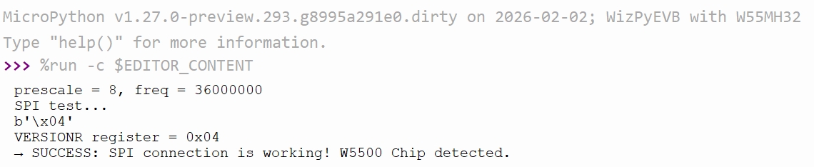
SPI
See machine.SPI.
SPI bus (WIZ850io)
Script: GitHub
YouTube Tutorial: Watch SPI demo video
- Setups:
Connect the SPI(1) with WIZ850io module.
Please based on the follow table to connect the WIZ850io with W55MH32.
WIZ850io |
W55MH32 |
|---|---|
GND |
GND |
VCC |
3V3 |
SCLK |
PA5 (SPI1_SCK) |
MOSI |
PA7 (SPI1_MOSI) |
MISO |
PA6 (SPI1_MISO) |
SCSn |
PA4 |
RSTn |
PA3 |
- Results:
It shows the correct chip version from W5500 chip’s register.
SPI bus (ST7789)
Script: GitHub
st7789py Library: GitHub
- Setups:
ST7789 |
W55MH32 |
|---|---|
GND |
GND |
VCC |
3V3 |
SCL |
PA5 (SPI1_SCK) |
SDA |
PA7 (SPI1_MOSI) |
RST |
PD6 |
DC |
PD5 |
CS |
PA4 |
BL |
3V3 (100% brightness) |
- Results:
It will display the following result.
SD Card
See machine.SDCard.
Script: GitHub
YouTube Tutorial: Watch SD Card demo video
- Setups:
Insert a microSD card into the SD card slot on the W55MH32 board.
- Results:
A file named “testing.txt” is written to the “/sd/” directory on the SD card.
The content “Hi from W55MH32!” is written to the file.
The script reads the content back from “testing.txt”.
The content is printed on the MicroPython shell.
USB
Setups: Connect the USB cable to the USB device port on W55MH32.
YouTube Tutorial: Watch USB demo video
USB VCP Mode (Virtual COM Port Only)
See machine.USB_VCP.
Script: GitHub
- Setups:
Turn on PuTTY (or any serial terminal).
Type and send a message from PuTTY to the board.
- Results:
The board will echo back whatever message was received.
USB MSC Mode (Mass Storage Only)
Script: GitHub
- Setups:
Run the script to enable USB MSC mode.
The board will appear as a USB flash drive on your computer.
- Results:
A file named “test.txt” is written to the USB flash drive.
The script reads the content back from “test.txt”.
The content is printed on the MicroPython shell.
WDT (Watchdog Timer)
See machine.WDT.
Script: GitHub
YouTube Tutorial: Watch WDT demo video
- Setups:
Run the script to enable the hardware watchdog with a 3‑second timeout.
Observe the first demo (with
wdt.feed()) – the program runs all 6 iterations.Comment out the
wdt.feed()line and rerun to see the unsafe behaviour.
- Results:
- Safe demo – The watchdog is fed every second. No reset occurs.
- Unsafe demo – Without feeding, the watchdog expires after 3 seconds and forces a system reset. The board reboots automatically.
PWM (Pulse Width Modulation)
See machine.PWM.
Script: GitHub
YouTube Tutorial: Watch PWM demo video
- Setups:
Connect the servo: signal wire to PA0, power to 5V, ground to GND on the W55MH32L-EVB.
Run the script to initialise PWM on PA0 at 50 Hz.
Watch the servo move to 0°, then 90°, then 180°, and finally sweep back and forth.
- Results:
The servo moves precisely to each angle (0°, 90°, 180°) and holds the position.
After the fixed positions, the servo sweeps smoothly back and forth in 10° increments.
The MicroPython shell prints the current angle and duty cycle for each step.
Music
See : Music and machine.Pin.
Script: GitHub
YouTube Tutorial: Watch Music demo video
- Setups:
Connect a passive buzzer (or small speaker) to pin PD15.
Provide common ground between the buzzer and the board.
- Results:
The script plays the built‑in melody
music.PUNCHLINEthrough the buzzer. The playback is blocking – the program waits until the melody finishes before printingDone..
I2S Audio
See machine.I2S and machine.SDCard (for SD card access).
W55MH32 |
Microphone (INMP441) |
Speaker (MAX98357) |
|---|---|---|
PB3 |
SCK |
BCLK |
PA15 |
WS |
LRC |
PB5 |
SD |
DIN |
3V3 |
VDD |
Vin + SD |
GND |
GND + L/R |
GND |
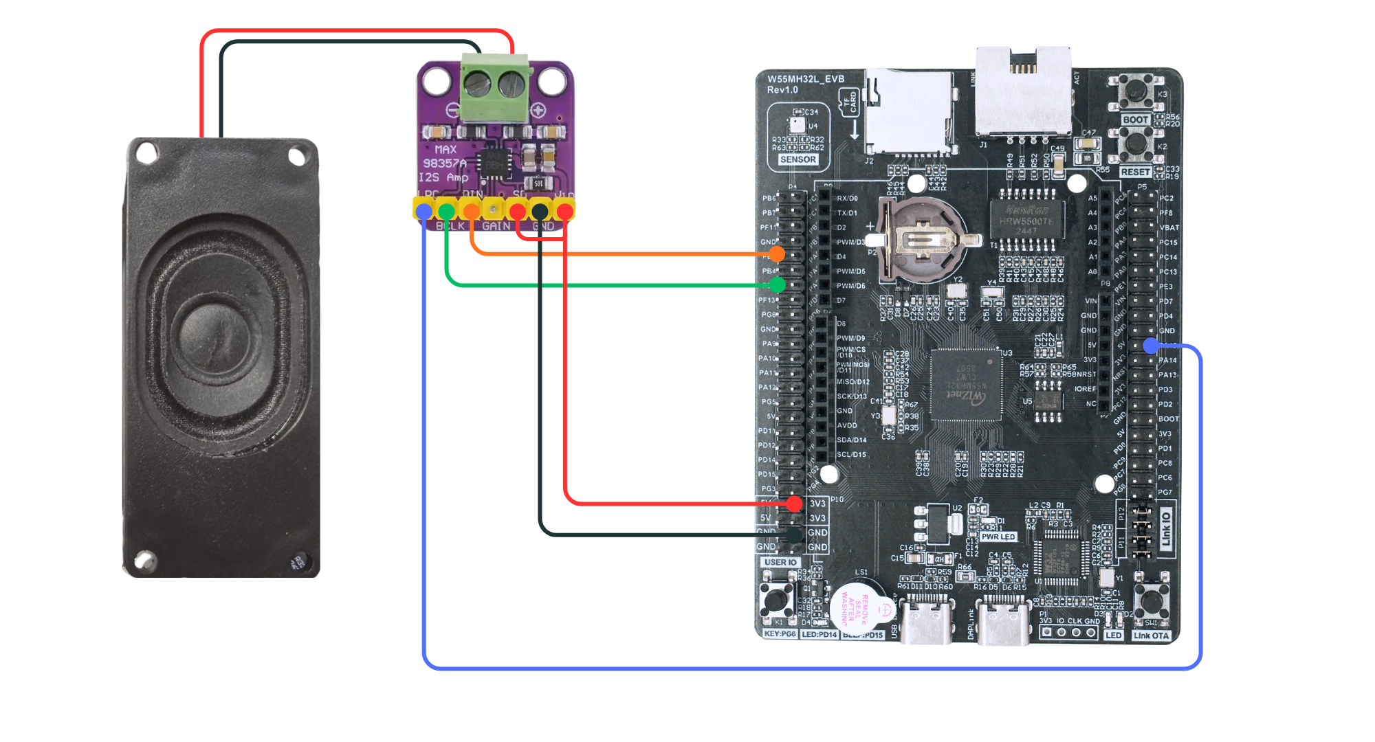
I2S Audio Playback (WAV)
Script: GitHub
YouTube Tutorial: Watch I2S playback demo
- Setups:
Connect an I2S amplifier (e.g., MAX98357) to the board: PB3 (BCLK), PA15 (LRC), PB5 (DIN). Connect speaker to the amplifier.
Place a stereo 44.1 kHz 16‑bit WAV file named
bg.wavon the microSD card.Run the script – it plays only the first 15 seconds of the file.
- Results:
The board reads the WAV file from the SD card and streams audio via I2S.
You hear the first 15 seconds of the song through the speaker.
The console prints “Played first 15 seconds” when done.
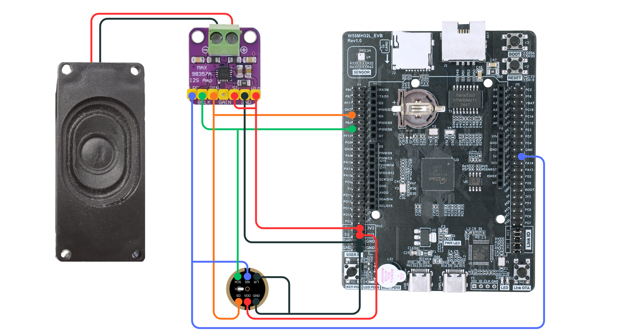
I2S Voice Recorder & Player
Script: GitHub
YouTube Tutorial: Watch voice recorder demo
- Setups:
Connect an I2S microphone (e.g., INMP441) to PB3 (BCLK), PA15 (LRC), PB5 (DIN). Connect an I2S amplifier + speaker to the same pins.
Connect a button to pin PG8.
Insert a microSD card to store recordings.
- Results:
Hold the button – the LED turns on, and the board records from the mic until you release.
Release the button – the recording is saved as
memo.wavon the SD card.The board immediately plays back the recorded audio through the speaker.
The console prints “Recording…” and “Done”.
MP3 Audio Playback
Script: GitHub
YouTube Tutorial: Watch MP3 playback demo
- Setups:
Connect an I2S amplifier + speaker to pins PB3 (BCLK), PA15 (LRC), PB5 (DIN).
Place an MP3 file (mono or stereo, any sample rate) on the microSD card.
Run the script – it decodes the MP3 in software and plays it through I2S.
- Results:
The board reads the MP3 file from the SD card, skips ID3 tags, and decodes frames.
Audio plays through the speaker at the original sample rate.
The console prints frame numbers and free memory every 100 frames.
“Done” appears when playback finishes.