Quick Reference For WIZio-RTU
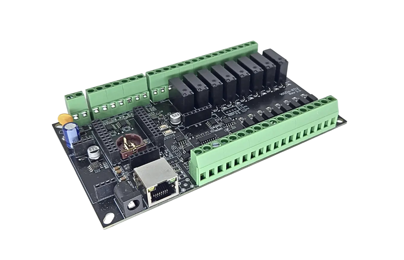
WIZio-RTU is a high-performance industrial control board developed by WIZnet’s W55MH32Q chip, specifically designed for industrial field applications. With its flexible power supply options, extensive interface configurations, and reliable control core, it meets diverse industrial automation control requirements.
Purchase link: WIZio-RTU
Download Hex file: WIZio-RTU hex
Firmware Information:
MicroPython version |
V 1.27.0 |
Release date |
2026/07/31 |
Release notes |
Minor fix in socket handling. |
Pinout
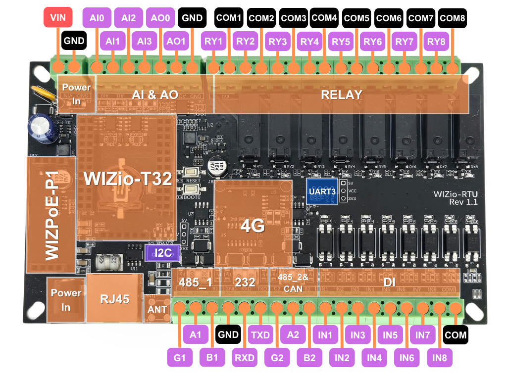
The pinout diagram below shows the available pins on the WIZio-RTU.
Frozen Modules
🧊 Click to expand – full list of frozen modules
Basic Setup
Basic Setup
Important
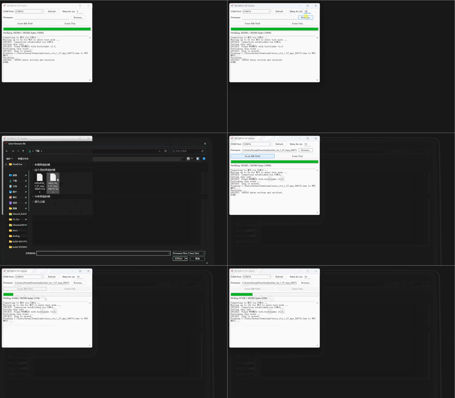
You will need WizISP Tool before using MicroPython on this board.
Connect the RS-232 (GND, RXD, TXD) terminal to your PC through a USB-to-serial adapter.
Unzip and open WizISP.exe.
Select the correct COM port and choose the firmware file you want to flash.
Click Erase && Flash.
To enter boot mode, press and hold the BOOT0 button first, then press the RESET button.
Once flashing is finished, open your preferred MicroPython REPL tool. You should see the MicroPython terminal start successfully. You can verify the firmware by running:
print("hello world!")
HTTP Configuration
Important
Visit WIZio-RTU HTTP Configuration for the source code of this project.
The WIZio-RTU HTTP Configuration Server runs a lightweight web server on the board, allowing users to configure and control the device from a web browser or HTTP client.
Through the web interface, users can configure network settings, control I/O channels, read analog values, send and receive serial/CAN data, access EEPROM storage, and use the 4G module.
After cloning the WIZio-RTU HTTP Configuration Server repository to your PC, upload all project files to the device. Once the upload is complete, reset the device to start the HTTP configuration program.
Warning
Sometimes Syntax Error may arise due to bad file writes. If you found this error, just reupload the given file and it should be good to go.
When the board boots, main.py enables garbage collection, imports http_app.py, and calls start(). The start() function then runs the HTTP server. After the network is initialized, the console prints the board address in this format:
Welcome to MicroPython WIZio-RTU. Visit http://<board-ip>:80 to configure your board.
Open that address in a browser to access the web interface.
Startup Flow
main.pyenables garbage collection and importshttp_app.py.http_app.pycreates aDeviceobject for hardware access.http_app.pyalso creates aServerobject and registers all HTTP routes.server.run()initializes the WIZnet network interface.The server listens on TCP port
80.For every HTTP request, the server reads the header, reads the body if a
Content-Lengthis present, matches the route, and sends a response.
HTTP Config Table of Contents
Web Page Demonstration
Network Config
DHCP:
Static:
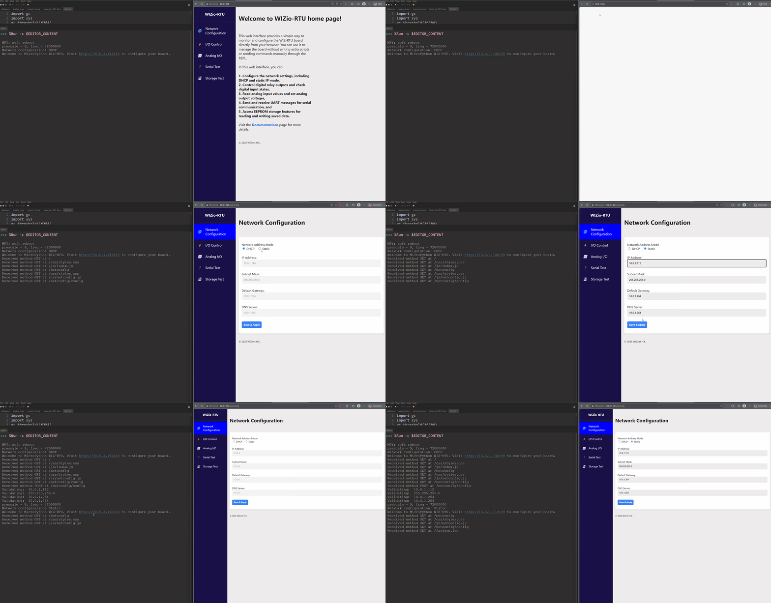
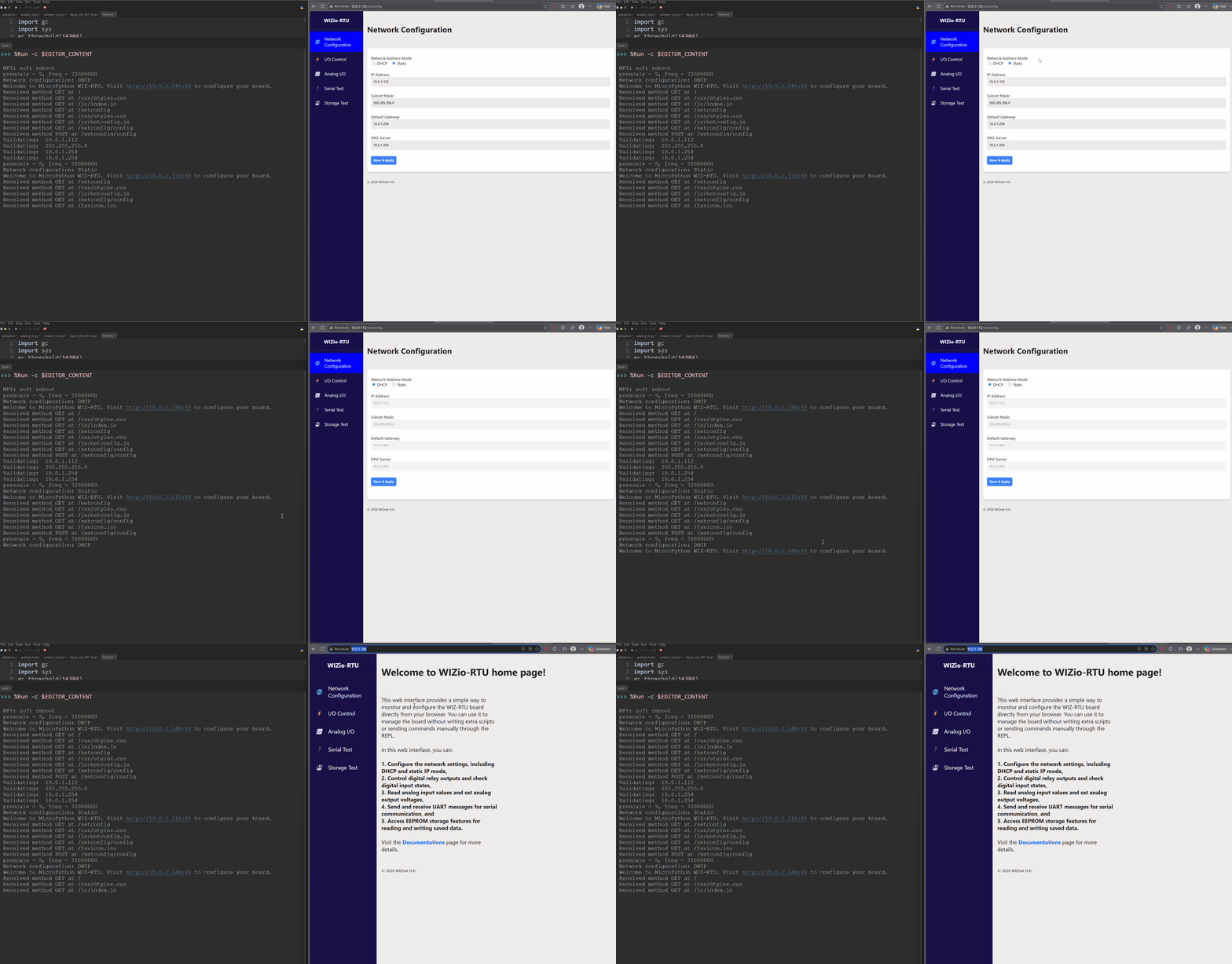
The Network Configuration tab allows users to view and change network details of the WIZio-RTU board.
When accessed, the tab first retrieves the current network settings from the device.
If DHCP mode is selected, the network information cannot be edited manually.
If Static mode is selected, you need to enter the correct network addresses before submitting the configuration.
After submission, the redirect behavior depends on the selected mode:
In DHCP mode, click the URL shown in the MicroPython REPL terminal to open the new web page.
In Static mode, the web page will automatically redirect to the new IP address.
Digital I/O
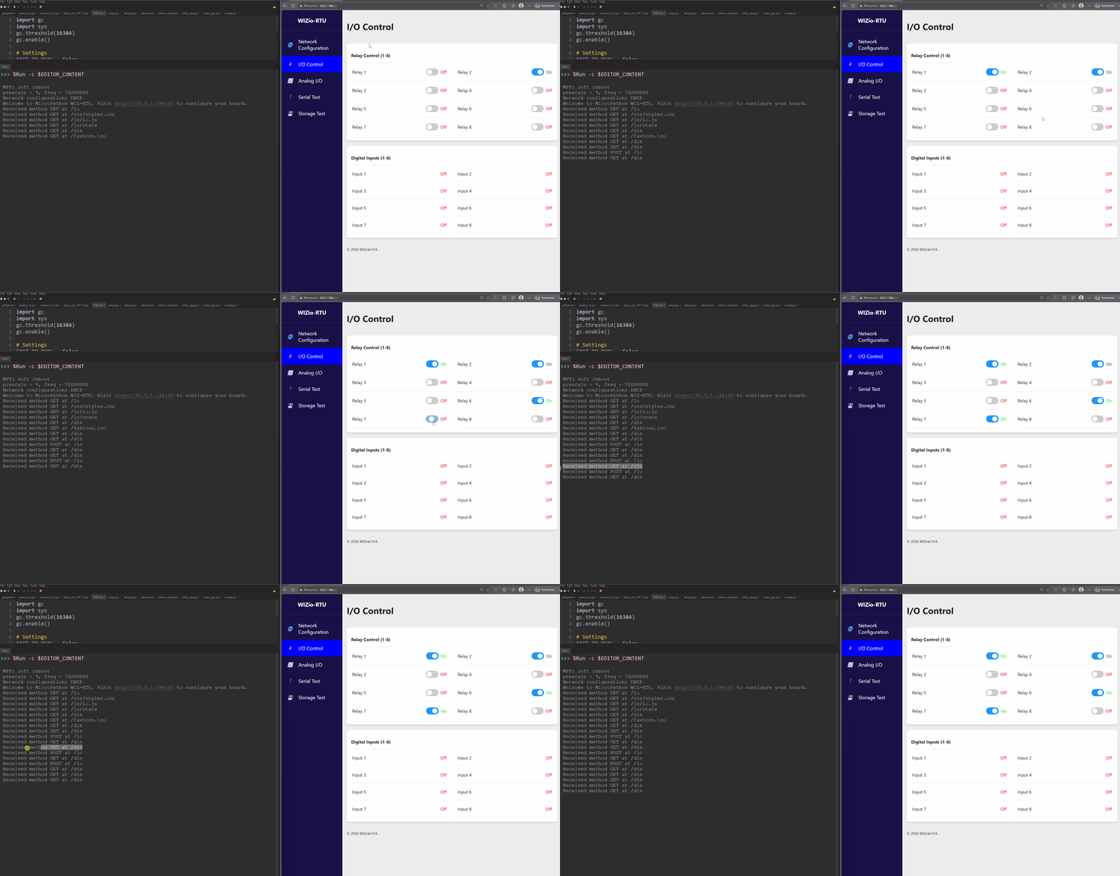
Upon entering the I/O Control interface, you can click each relay button to change its output state.
When a relay is activated, the corresponding relay LED on the WIZio-RTU board will turn on, and a clear clicking sound can be heard from the relay.
For digital inputs, the web interface continuously polls the input channel states. When an input circuit is active, the corresponding input LED on the WIZio-RTU board will turn on, and the channel status will be displayed as ON in the web interface.
Note
Reading Inputs: Each fetch interval queries the
/dinAPI endpoint to retrieve the real-time status of the input pins.Controlling Relays: Pressing the toggle button dispatches a
POSTpayload to the/ioAPI endpoint to update the relay states.
Analog I/O
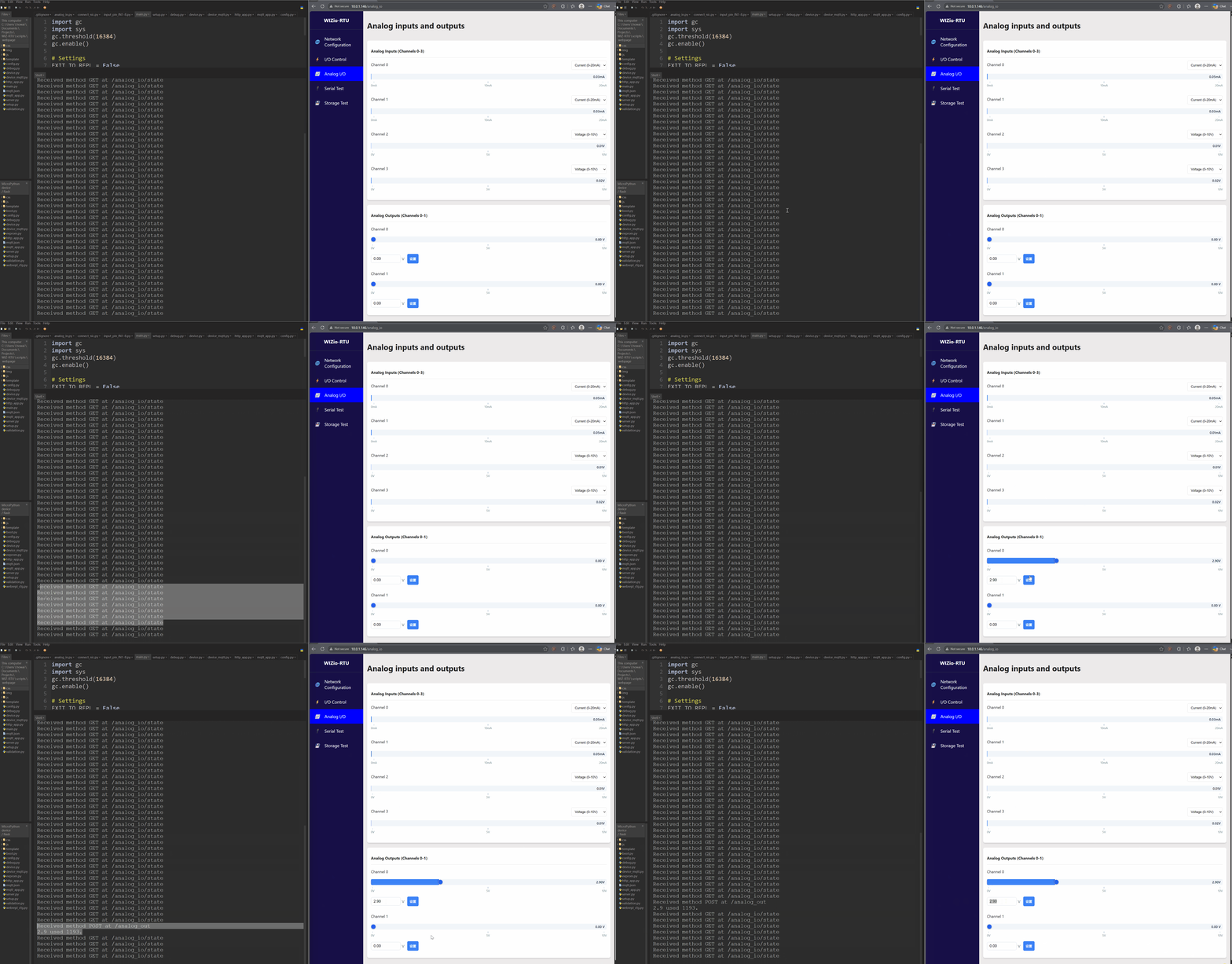
On the Analog I/O page, you may view the ADC values of your board.
The acquisition mode must match the board’s actual operating mode.
In the ADC section, the webpage automatically sets the operating mode according to the board’s software configuration. See device.py for the implementation details.
To view or change the acquisition mode, install the required resistors in the operating-mode circuits. For guidance, visit WIZio-RTU, download the WIZio-RTU user manual, and refer to Section 2.7.
Note
/analog_out uses a POST request to send the desired DAC output value to the device.
/analog_input/state retrieves the current ADC input values from the device.
CAN
Send:
Receive:
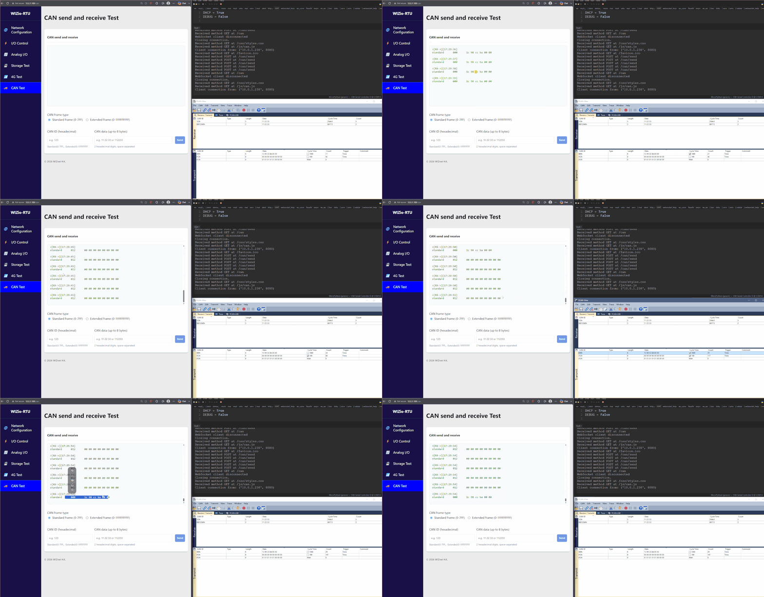
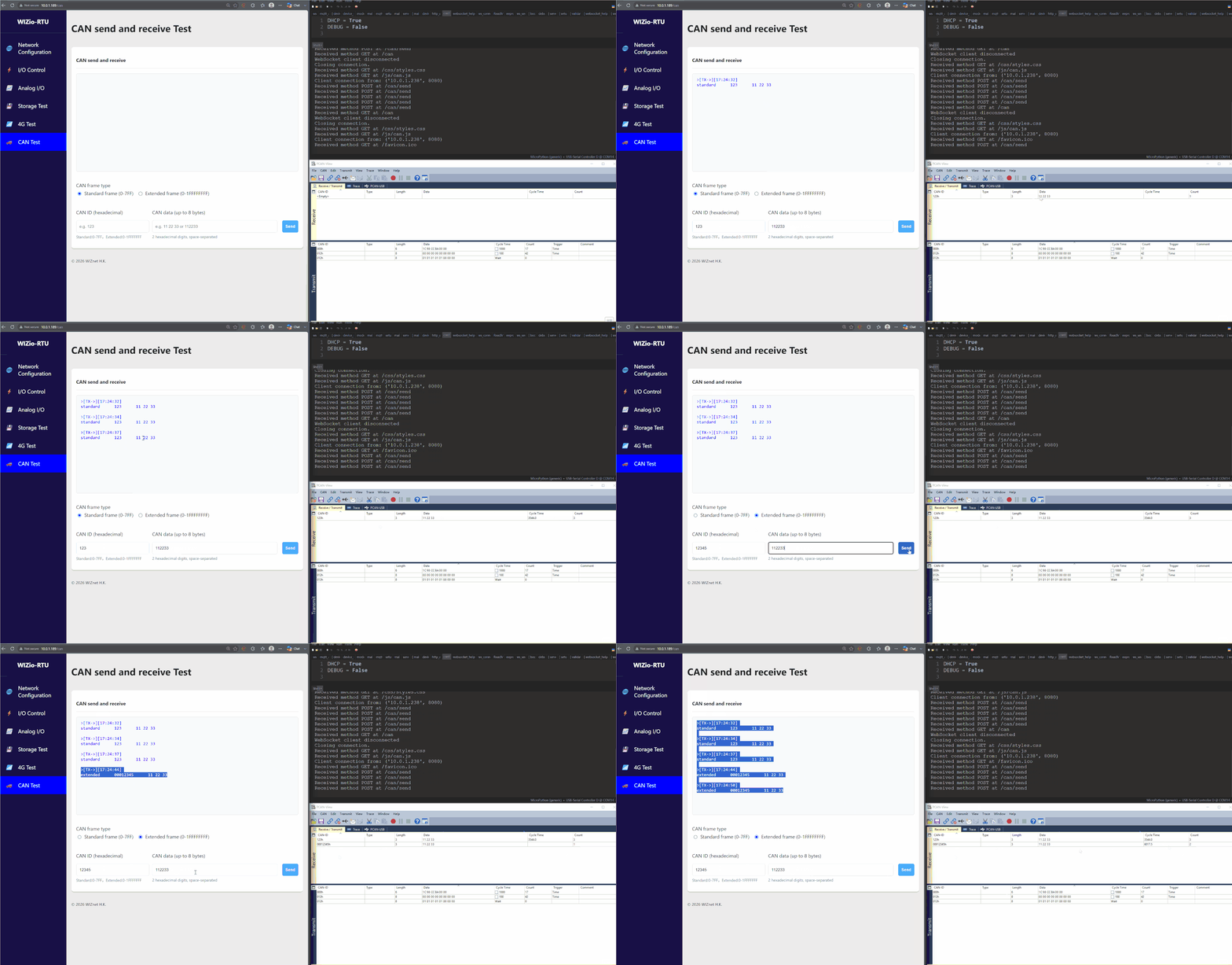
On CAN page, you can send and receive data through the UART transmission line using pins A2, B2, and GND.
Before starting to use the CAN bus, it is important to set the CAN_CONFGIS under config.py. By default, the CAN uses 500000 as its baudrate and uses CAN.NORMAL mode for data exchange.
This demostration uses PCAN-View so as to visualize the CAN data being successfully transmitted.
To send the data to the view, you would need to first choose between Standard or Extended frames, then input the target ID before sending any data.
On receive, you will automatically receive data from various ID. The page will automatically shows whether the received frame is in Standard or Extended format.
Serial
Important
Currently, all RTU boards will come in CAN instead of RS485 for terminal (G2, A2, B2).
To enable RS485, you would need to resolder according to the schematics and set CAN_MODE to False inside config.py.
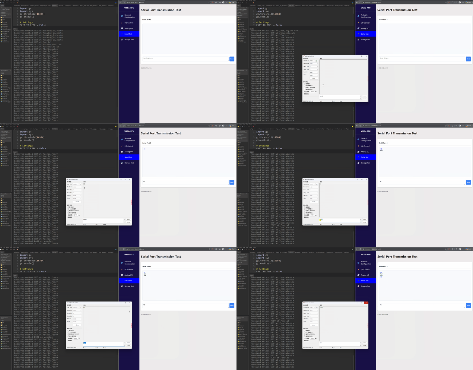
On the serial page, you can send and receive data through the UART transmission line using pins A2, B2, and GND. This connection corresponds to RS485 interface 2.
The webpage continuously polls for UART data. When data is received from the device, it is displayed in the webpage terminal.
You can use the WIZnet Serial Debugging Tool located on the index page for this test. Make sure all serial parameters match the UART_CONFIG settings in config.py.
Storage
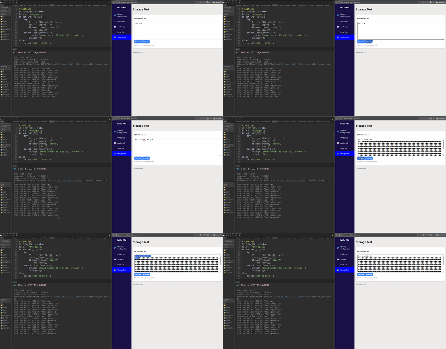
On the WIZio-RTU, the on-board EEPROM is connected to the board’s I2C line. You can read data from, or write data to, the EEPROM.
See eeprom.py for detailed usage of the EEPROM device.
Note
The EEPROM may be used to store binary data. Therefore, data that cannot be decoded as UTF-8 is displayed as � on the webpage. This is expected behavior.
4G Module/Modem
Note
This demonstration uses the 4G module FS-LCore-F8X0M2 by Feisichuang.
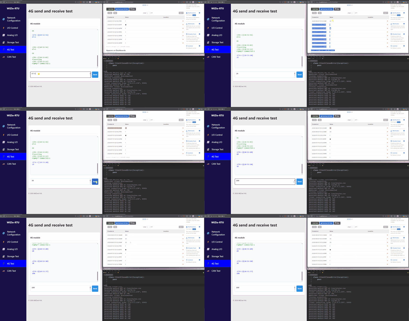
Upon demonstration uses MQTT as the workmode and connects to Adafruit IO. The 4G module is controlled by the WIZio-RTU’s UART4 terminal, which we can type commands to.
To configure the 4G module as an MQTT client, use the following AT commands.
Important
Each AT command must be followed by a line break. The +++ escape sequence is the only exception and must be sent without a line break.
# Enter command mode
+++

# Set the working mode to MQTT
AT+WKMOD1=MQTT

# Set the MQTT broker address and port
AT+MQTTSV1=io.adafruit.com,1883

# Set the MQTT client credentials and connection parameters
AT+MQTTCONN1=<client_id>,<username>,<password>,<keepalive>,<clean_session>

# Set the MQTT endpoint to publish to
# e.g. AT+MQTTPUB[CH]=<topic>,<qos>,<retain>
AT+MQTTPUB1=arnoldho/feeds/light,0,0

# Save the configuration and restart the module
AT+S
On restart, you should wait until FS@MQTT CONNECTED:1 is shown, then you can type any value to publish to the MQTT endpoint.
Customizing the HTTP Application
The HTTP server uses http_app.py to define the web routes and the behavior behind each page or API request.
Edit http_app.py if you need to customize the HTTP application for your own peripheral needs. For example, you can change what happens when a relay is switched, when an input value is read, when a UART message is received, or when a new HTTP request is handled.
The lower-level files should normally be kept unchanged:
server.pyhandles the HTTP connection, request parsing, response sending, and route dispatching.device.pyprovides the basic hardware control functions for the WIZio-RTU board.
For most user customizations, only http_app.py needs to be edited.
Below you can find a more detailed explanation of each section of the HTTP webpage.
MQTT Device
Important
Visit WIZio-RTU MQTT Device for the source code of this project.
Similar to the HTTP configuration interface, the MQTT-enabled application allows the WIZio-RTU to be monitored and controlled remotely through an MQTT broker.
With the MQTT interface, users can:
Control relay outputs by switching individual relays on or off
Monitor digital inputs and receive updates when an input state changes
Measure analog inputs in either current mode or voltage mode
Generate analog output voltages of up to approximately
10 VSend and receive serial data through the onboard UART interface
Access the onboard EEPROM, including write, read, and wipe operations
Monitor device states remotely using retained MQTT state messages
Integrate the WIZio-RTU with dashboards, automation systems, and IoT platforms
Visit MQTT Topics Summary for the default topics.
The MQTT application is suitable for remote monitoring, industrial control, equipment testing, and automation projects where the WIZ-RTU needs to exchange data with other devices or software services.
Note
To test the MQTT functionalities of the board, you can run the MQTTDashboard script under the above repo.
Make sure you download Eclipse Mosquitto on your PC and start your MQTT Broker.
MQTT Demonstration
MQTT device Table of Contents
MQTT Setup
Clone the project and upload all files except mqtt.default.json to the device. The
application starts from main.py, which imports mqtt_app.py and runs the
MQTT device loop.
Before starting the application:
Copy
mqtt.default.jsontomqtt.jsonifmqtt.jsonis not already present.Set the MQTT broker address and port in
mqtt.json.Add the MQTT username and password when the broker requires authentication.
Check the hardware settings in
config.py. The supplied configuration uses DHCP and RS485/UART at9600baud, with 8 data bits, no parity, and 1 stop bit.Upload the Python files and JSON configuration to the board, then reset it.
Example mqtt.json:
{
    "host": "192.168.1.100",
    "username": null,
    "password": null,
    "port": 1883
}
Network Config
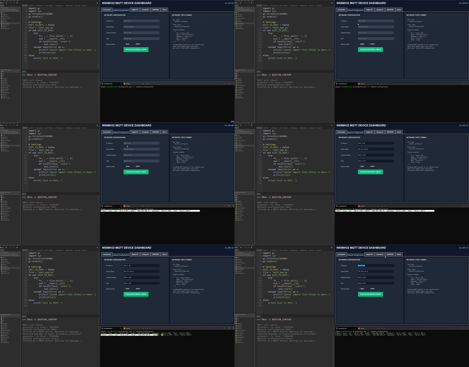
DHCP to Static
Static to DHCP
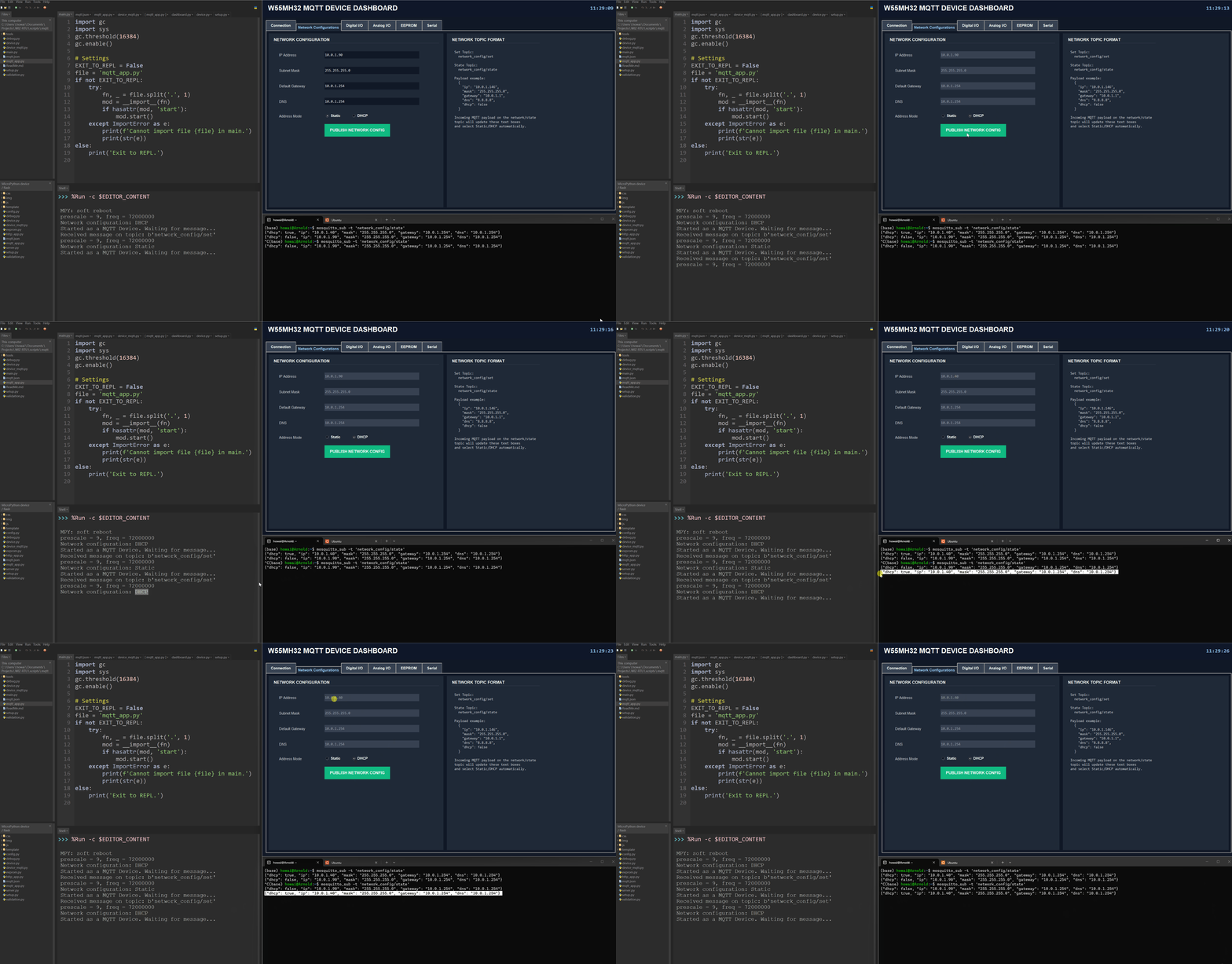
WIZio-RTU uses two MQTT topics for network configuration:
network_config/statepublishes the current network settings.network_config/setapplies new network settings submitted by the user.
After a new configuration is submitted, the network interface is updated and a restart flag is set. DeviceMQTT.run() detects this flag, restarts the MQTT connection, and reconnects to the broker using the updated network settings.
Digital I/O
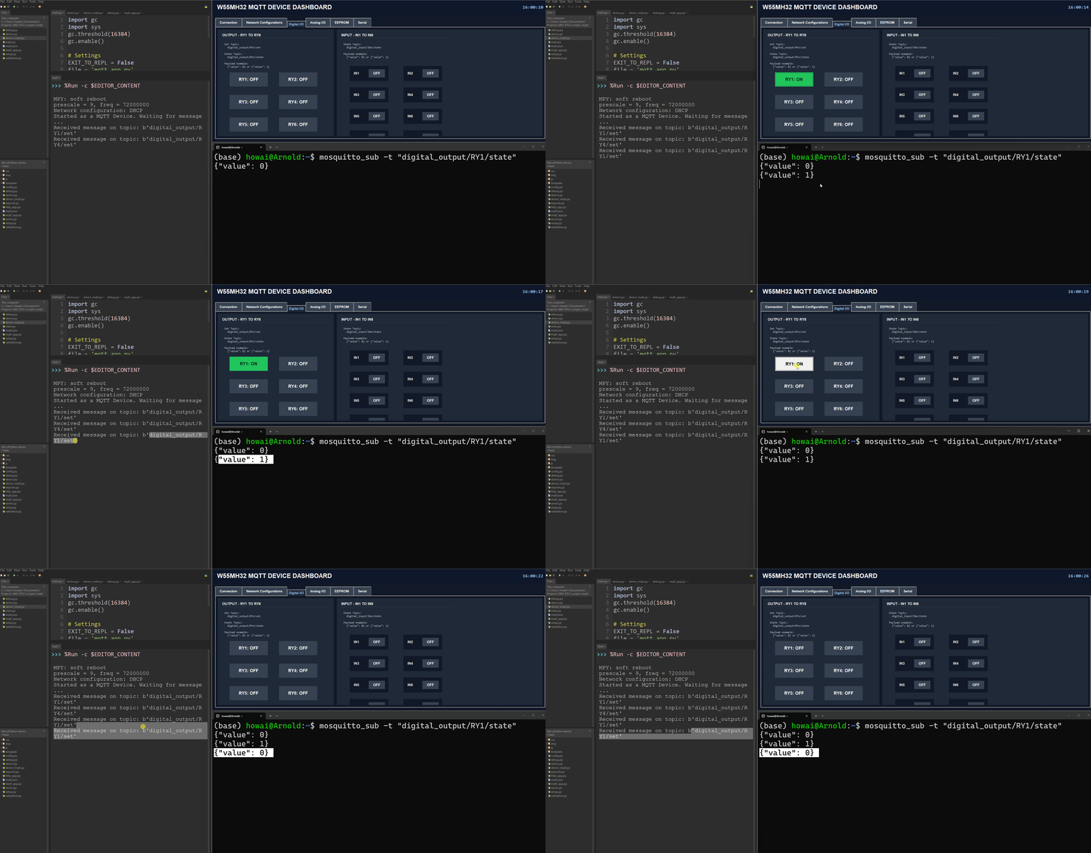
For WIZio-RTU’s MQTT digital outputs, when a value is submitted through the dashboard, it is published to the digital_output/+/set topic, where the + wildcard represents the selected relay pin RY[1-8].
After receiving the command, the device updates the relay and publishes its current state to digital_output/+/state.
A value of 1 (HIGH) turns the relay on, while 0 (LOW) turns it off.
Note
When the relay is activated successfully, you should hear an audible click and see the corresponding relay LED turn on.
For WIZio-RTU’s MQTT digital inputs, the device polls under device._poll_din() and checks whether there are changes in the pin.
When a change is detected, the device publishes to the corresponding pin IN1-8 under digital_input/+/state with message
{
    "value": 1
}
Note
When the input forms a complete circuit, you should see the corresponding input LED turn on.
Analog I/O
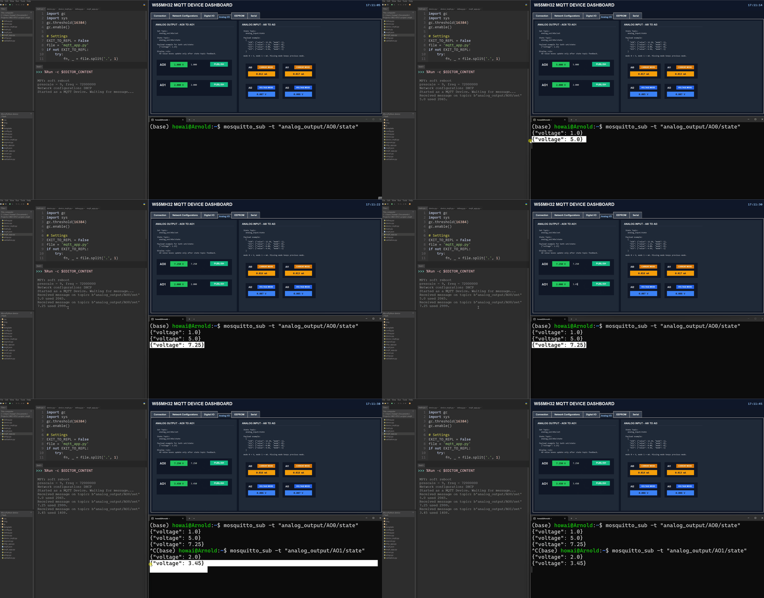
For WIZio-RTU’s MQTT analog outputs, when a value is submitted through the dashboard, it is published to the analog_output/+/set topic, where the + wildcard represents the selected relay pin AO0 or AO1.
After receiving the command, the device updates the analog output and publishes its current state to analog_output/+/state.
Both the command and state messages use the following JSON format:
{
  "voltage": 1
}
The range of voltage must be in between (0 - 10) V.
Note
To verify the voltage, you can use a multimeter to measure across AOx to the GND terminal.
The WIZio-RTU board provides four analog inputs, from AI0 to AI3. The device periodically measures all analog inputs and publishes their current readings to:
analog_input/state
The published message uses the following JSON format:
{
  "AI0": {
    "value": 12.3,
    "mode": 1
  },
  "AI1": {
    "value": 11.8,
    "mode": 1
  },
  "AI2": {
    "value": 2.5,
    "mode": 0
  },
  "AI3": {
    "value": 3.1,
    "mode": 0
  }
}
AI0 and AI1 operate in current mode and report values in milliamperes (mA), while AI2 and AI3 operate in voltage mode and report values in volts (V).
Important
The dashboard updates automatically based on each 10 readings and submits a average value among the 10 values.
CAN
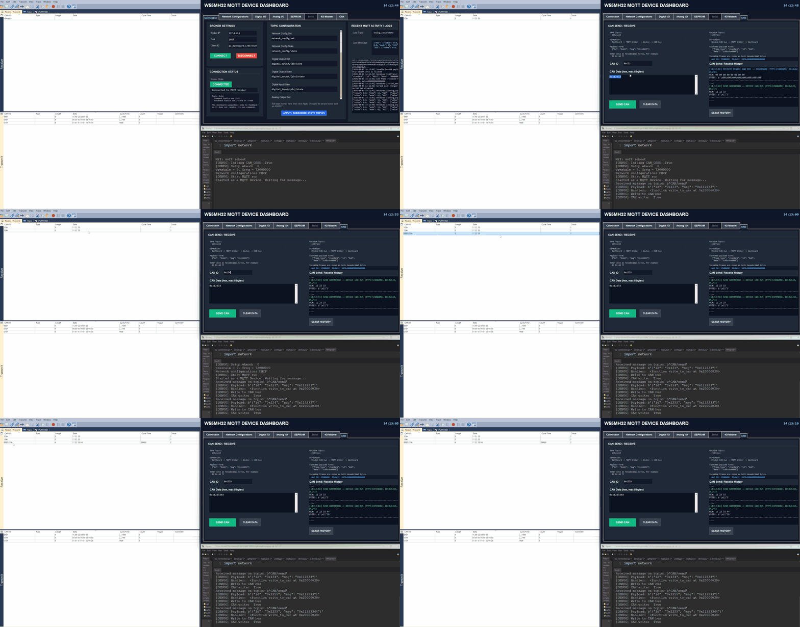
Send:
Recv:
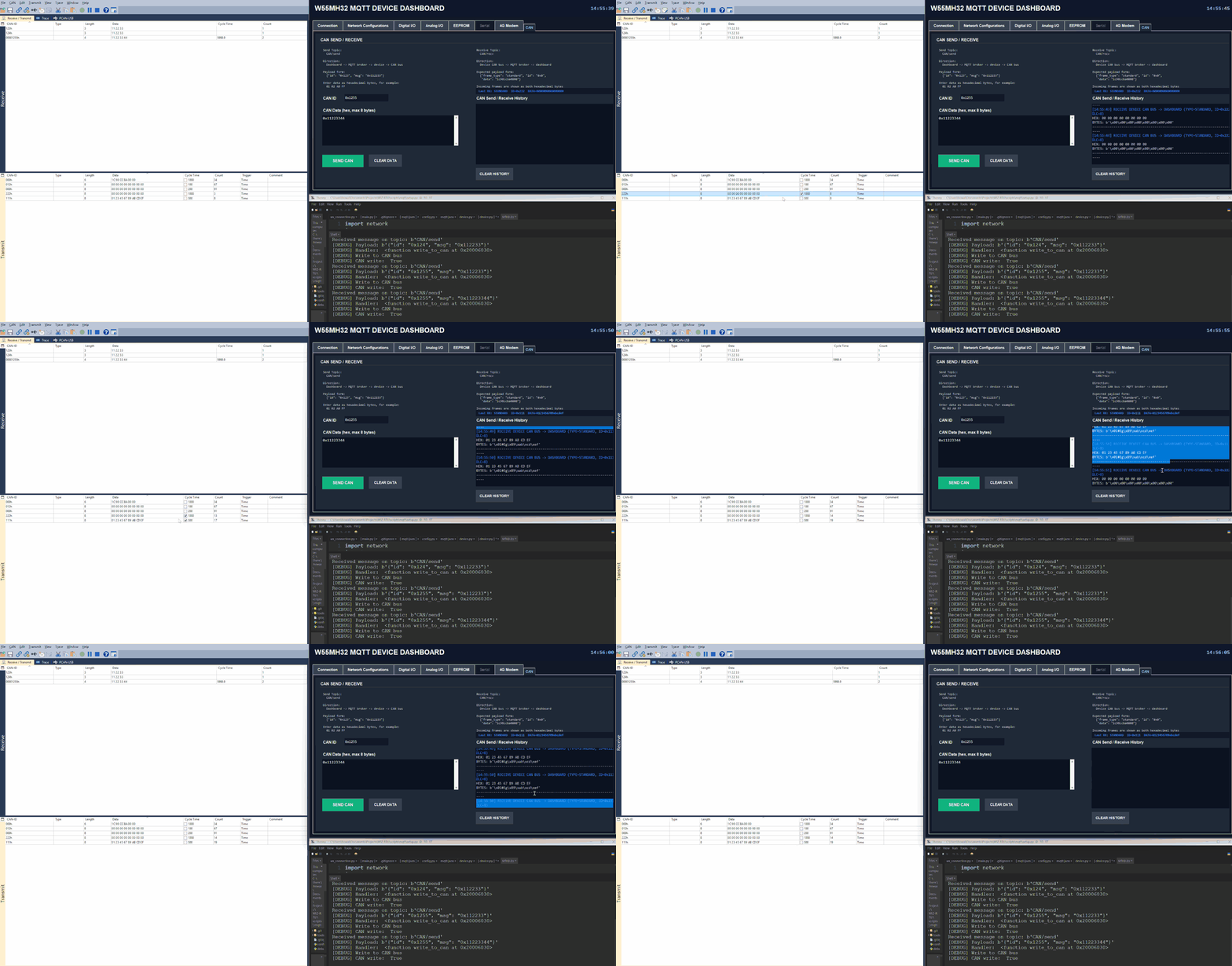
Similarly to the HTTP version, the MQTT application can send and receive CAN frames on the WIZio-RTU. The hardware setup and CAN bus settings are the same as the HTTP application, including the CAN baudrate, mode, frame type, and wiring.
For the CAN hardware configuration, see HTTP-CAN. In the MQTT project, the same CAN settings can be changed in config.py.
Serial
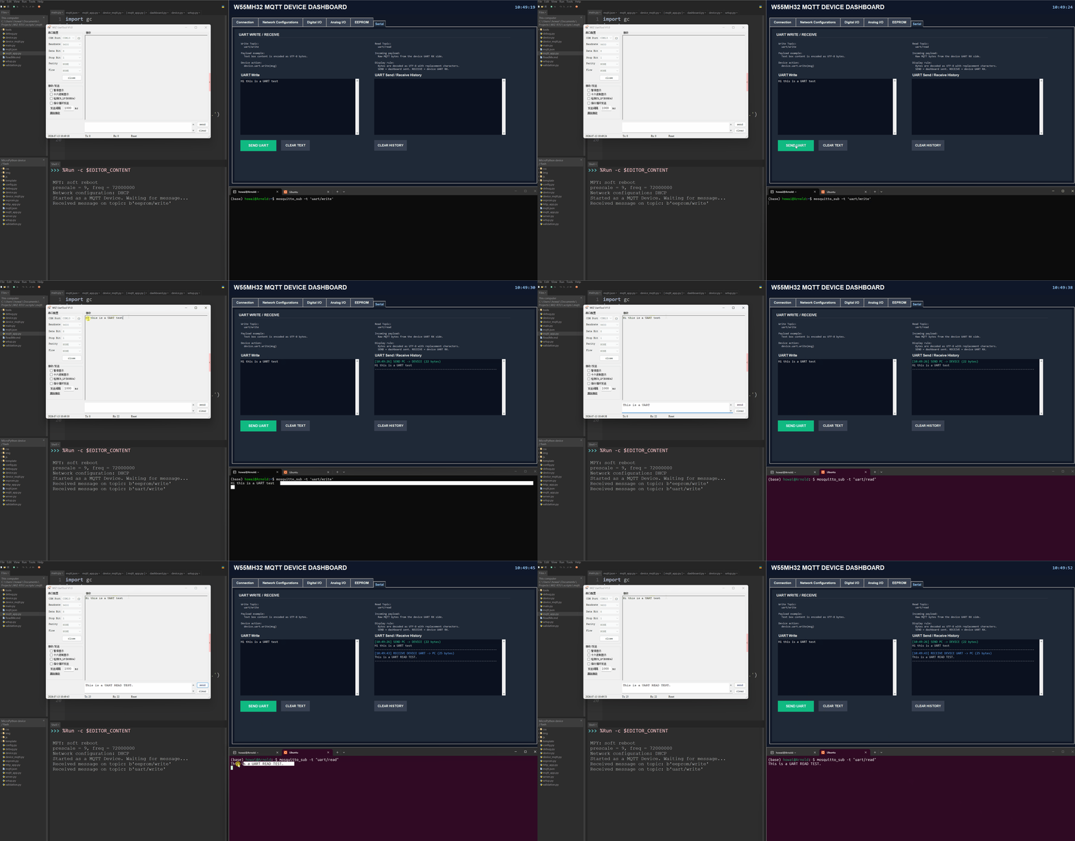
WIZio-RTU MQTT UART communication uses the following topics by default:
uart/write— Sends data from the MQTT client to the WIZio-RTU UART interface.uart/read— Publishes data received by the WIZio-RTU UART interface.
Use the WIZnet Serial Debugging Tool during testing to send and receive serial data and verify that UART communication is working correctly.
Storage/EEPROM
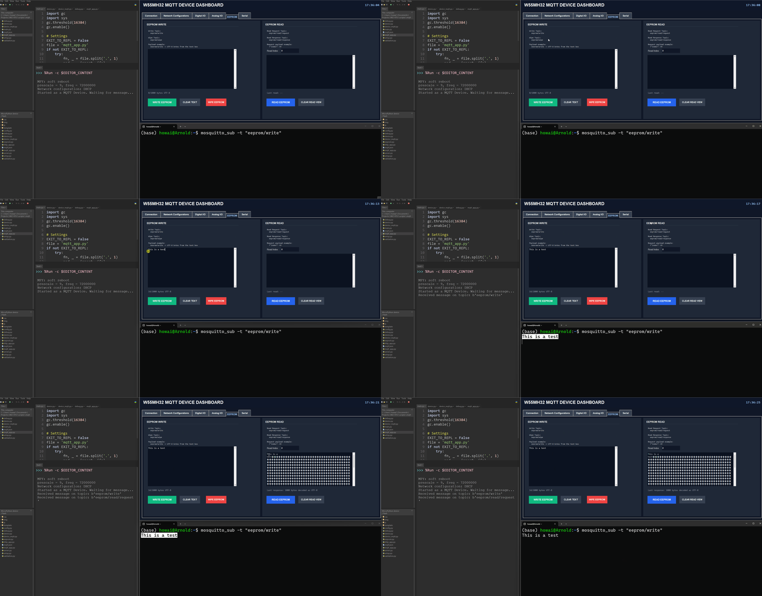
For WIZio-RTU MQTT EEPROM, there consist of four important topics regarding to normal R/W operations.
eeprom/writeeeprom/read/requesteeprom/read/responseeeprom/wipe
The write and wipe operations are straightforward. Data published to eeprom/write is converted to bytes and stored in the EEPROM, while publishing the expected command to eeprom/wipe clears the stored EEPROM data.
Reading data requires a request-and-response process. First, publish a message to eeprom/read/request using the following payload:
{"index": integer}
The index value specifies the EEPROM location from which reading should begin. After processing the request, the device publishes the retrieved data as bytes to eeprom/read/response. Any MQTT client subscribed to this topic can then receive the EEPROM contents.
Note
To receive updated EEPROM data, subscribe to the eeprom/read/response topic is enough.
4G Module/Modem
Note
This demonstration uses the 4G module FS-LCore-F8X0M2 by Feisichuang.
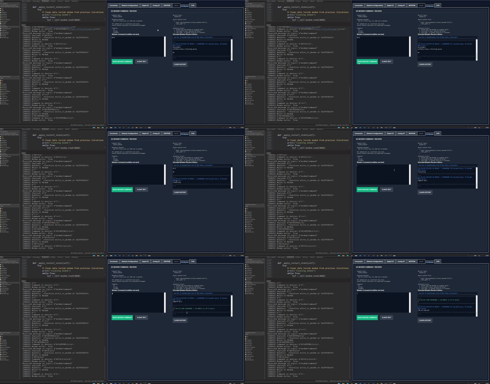
Different from the HTTP-Modem, the upon demo shows the 4G Module sending a HTTPS GET request to ifconfig.me\ip.
To send a HTTP GET request, use the following AT commands.
Important
Each AT command must be followed by a line break. The +++ escape sequence is the only exception and must be sent without a line break.
# Enter command mode
+++

# Set the working mode to HTTP
AT+WKMOD1=HTTP

# Set HTTP method to GET
AT+HTPTP1=GET

# Set SSL to On (Becuase the target link uses SSL)
AT+SOCKSSL1=ON

# Set the HTTP GET Endpoint
AT+HTPURL1=https://ifconfig.me/ip

# Save the configuration and restart the module
AT+S
On restart, you should wait until FS@HTTP OK:1 is shown, then you can type any value to retrieve the data.
Customizing MQTT Behavior
The MQTT application uses mqtt_app.py to define the topics that the device subscribes to and the functions that are executed when messages are received.
Edit mqtt_app.py when you need to customize the MQTT commands for your own peripheral or application requirements. For example, you can:
Add a new subscribed topic.
Change an existing subscribed topic.
Define what happens when a relay-control message is received.
Process commands for custom sensors or peripherals.
Change how incoming UART, EEPROM, analog-output, or network-configuration messages are handled.
Subscribed topics and their corresponding handler functions are registered using the add_topic() decorator:
@client.add_topic("custom/topic")
def handle_custom_topic(msg):
    print("Received:", msg)
When a message is received on custom/topic, the MQTT application automatically calls handle_custom_topic() and passes the received payload to the msg argument.
The lower-level files should normally be kept unchanged:
device_mqtt.pymanages the MQTT connection, topic subscriptions, message dispatching, publishing, device polling, and standard state updates.device.pyprovides the basic hardware-control functions for the WIZio-RTU board.mqtt.jsonstores the MQTT broker address, port, username, and password.main.pystarts the MQTT application by importing and runningmqtt_app.py.
For most MQTT application customizations, only mqtt_app.py needs to be edited.
In the default application structure,
mqtt_app.pymainly defines the subscribed command topics and the functions that handle their incoming messages, whiledevice_mqtt.pyhandles the functions for published state topics . The published topics report the current device state to the MQTT broker and connected applications.
Modify device_mqtt.py only when you need to change the underlying MQTT behavior, such as:
How the MQTT client connects or disconnects.
How topics are subscribed to and dispatched.
How device inputs are polled.
How frequently analog inputs are sampled.
How state messages are published.
How MQTT wildcard topics are matched.
How the MQTT run loop behaves.
Modify device.py only when you need to change the underlying hardware-control behavior, such as GPIO, ADC, DAC, UART, I2C, or EEPROM operations.
Below you can find a more detailed explanation of the available MQTT topics, their payload formats, and the corresponding device behavior.
- MQTT Application Overview
- Network and Broker Configuration
- MQTT Topic Summary
- Initial State and Retained Messages
- Network Configuration Topics
- Digital I/O Topics
- Analog I/O Topics
- CAN Topics
- Serial UART Topics
- EEPROM Topics
- 4G Modem Topics
- Runtime, Restart, and Error Behavior
- Customizing the MQTT Application
- Example Usage With Mosquitto
WebREPL
Important
Visit the W55MH32 WebREPL repository to download the source code for this project.
MicroPython WebREPL allows you to connect to and control your device remotely through a web browser.
Use the official MicroPython WebREPL client page to connect to and test your device.
Note
The network interface uses DHCP by default. To use a static IP address instead, open setup.py, update the network configuration values, and set the dhcp parameter to False.
Clone the repository and upload all .py files to the MicroPython device.
Open the terminal in your preferred MicroPython editor and run:
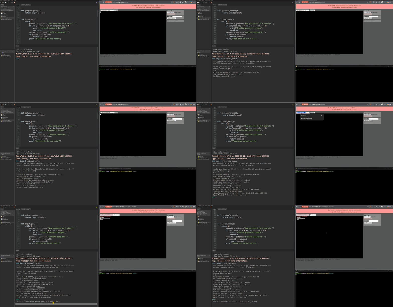
import webrepl_setupFollow the instructions shown in the terminal. After setup is complete, you will be asked whether you want to reboot the device.
If WebREPL on boot is enabled,
webrepl_w55mh32.pywill run automatically after the device restarts.When WebREPL starts successfully, the terminal will display a WebSocket address for connecting to the device.
Open the MicroPython WebREPL client page. Replace the default WebSocket address with the address displayed in the terminal:
ws://IP_ADDRESS:PORTClick Connect and enter the WebREPL password configured during setup.
After the connection is established, the MicroPython REPL prompt should appear in the browser.
Attention
Some MicroPython editors, such as Thonny, use Raw REPL mode. While Raw REPL is active, commands entered through the browser may not affect the device terminal.
To resolve this issue, close Thonny and reset the board before connecting through WebREPL. Alternatively, use mpremote to monitor and interact with the device.
Monitoring WebREPL with mpremote
mpremote can be used to monitor the device through its USB or serial REPL while testing a WebREPL connection from a browser. This is useful for viewing startup messages, connection attempts, and any errors reported by the board.
Install mpremote
Install mpremote by following the official MicroPython mpremote installation guide.
After installation, start mpremote using the command appropriate for your operating system.
On Linux:mpremote
On Windows:python -m mpremoteIf the board is connected and recognized by your computer,
mpremoteshould automatically connect to its serial REPL.
Note
Remeber to close any Raw-REPL terminal that uses the device.
Keep mpremote open so that you can monitor messages from the device.
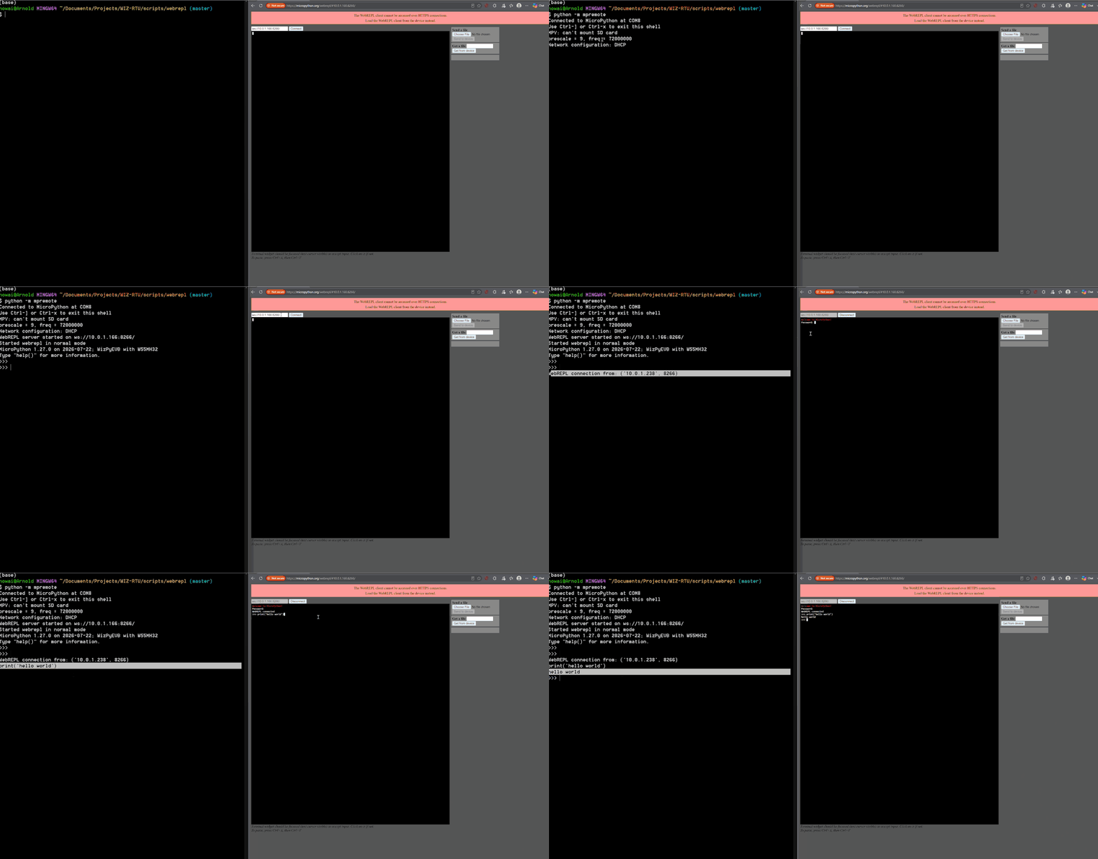
Then, on the MicroPython WebREPL page in your browse, test the connection with:
print("Hello, world!")
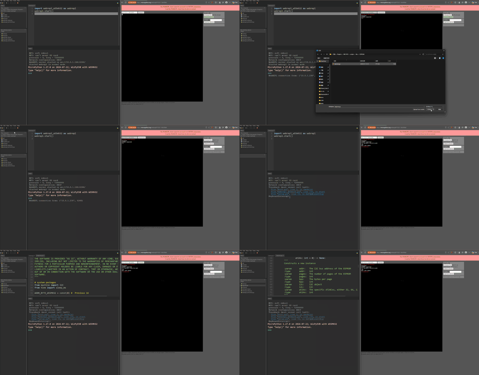
File transfer using WebREPL
WebREPL supports more than remote REPL access. It can also transfer files between the browser and the device.
The WebREPL interface provides two file-transfer operations:
Download a file from the device.
Upload a file to the device.
Important
Avoid modifying or replacing a file while it is being executed by the device. Stop the running program or return to the REPL before transferring application files.
For the following demonstration, I will use Thonny instead of WebREPL, since file transfer works also when Raw REPL is present and it is much more clearer.
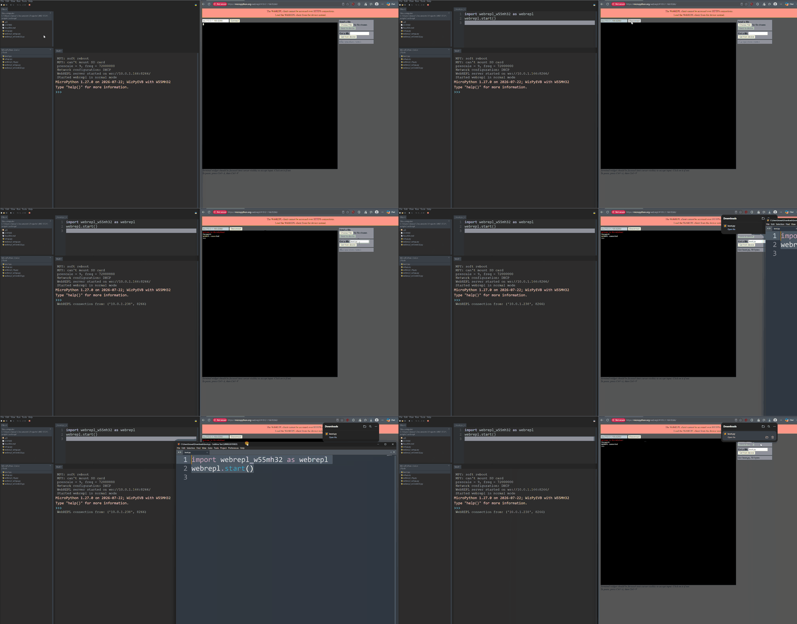
Download a File from the Device
Enter the name of the file stored on the device and use the WebREPL download control to save it to your computer.
Upload a File to the Device
Select a file from your computer and use the WebREPL upload control to transfer it to the device.
You can also run
import os
os.listdir()
to view if the file appeared in the system.
General Board Controls
You can find similar scripts as in W55MH32L-EVB.
Network
See Networking.
Delay and timing
See Delay and timing.
Pins and GPIO
Since some pins are being attached already to input/output/analog circuit, Most pins are being limited to its own functions.
for example, since IN1 is binded to an input circuit,
from machine import Pin
pin = Pin('IN1', Pin.OUT)
This will causes error:
>>> Pin('IN1', Pin.OUT)
Traceback (most recent call last):
  File "<stdin>", line 1, in <module>
ValueError: invalid pin mode: 1
Timer
See Timers.
RTC (real time clock)
ADC
See ADC (analog to digital conversion).
Note
ADC pins are only available on AI0/PA0, AI1/PA3, AI2/PA6 and AI3/PA7.
DAC
See DAC (digital to analog conversion).
Note
DAC pins are only available on AO0/PA4 and AO1/PA5.
SPI
See SPI bus
Attention
SPI is not available on the board except for the network interface of the W55MH32 chip.
I2C
There is a total of 2 sets of I2C pins on the board.
One is used for the onboard EEPROM, and one is not attached.
Please connect the onboard resistor in order to enable the second set of I2C pins.
See I2C bus
UART
See _uart_script
Note
UART are only available on UART(3) and UART(4). UART(3) is used by CAN/RS485 interface and UART(4) is used for Modem.