Quick Reference For W55MH32Q-EVB
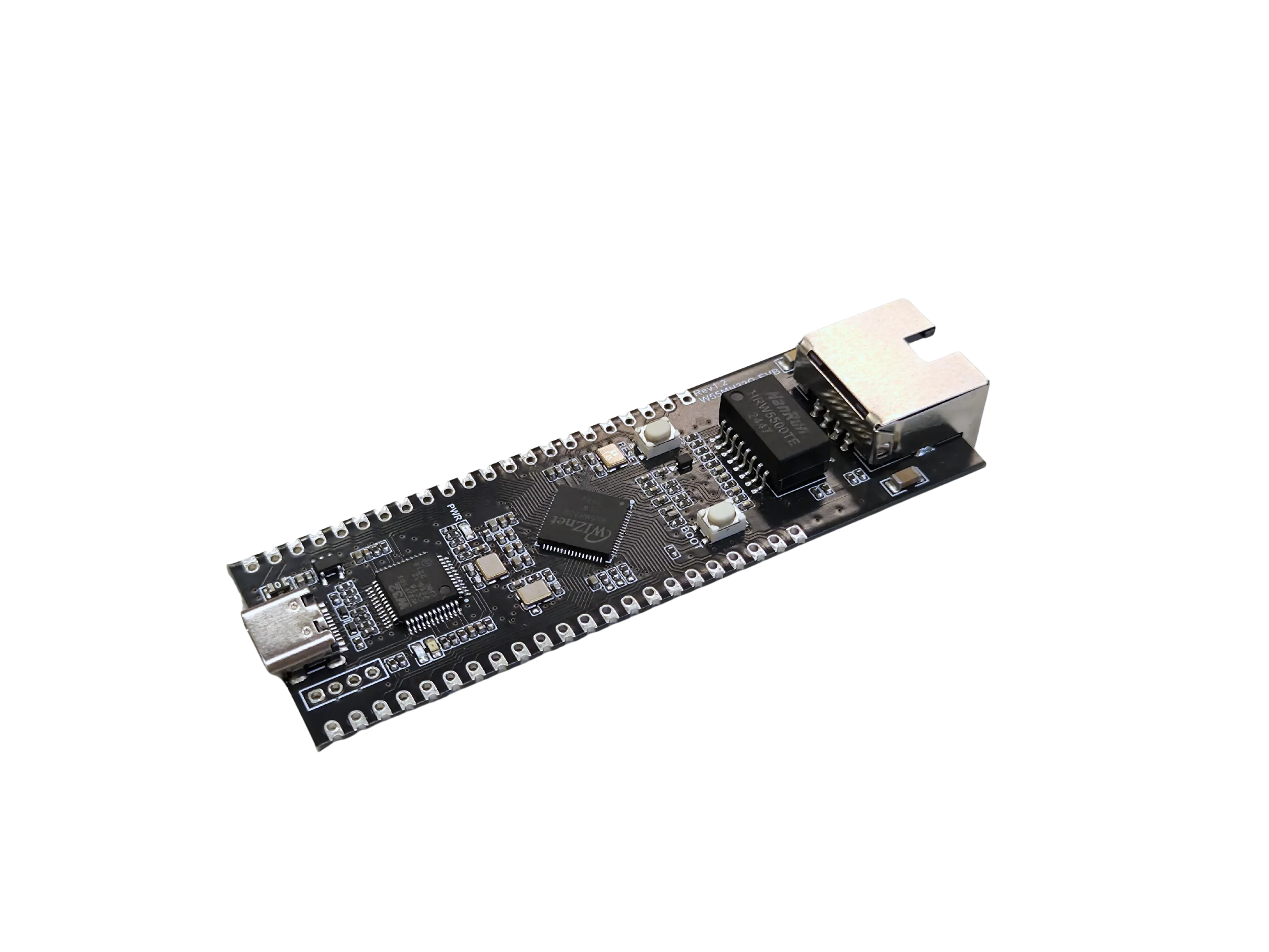
Purchase link: W55MH32Q-EVB
Download Hex file: W55MH32Q-EVB hex
Firmware Information:
MicroPython version |
V 1.27.0 |
Release date |
2026/07/20 |
Release notes |
This version is based on W55MH32L-EVB |
Below is a quick reference for the W55MH32Q-EVB. If it is your first time working with this board please consider reading this section first.
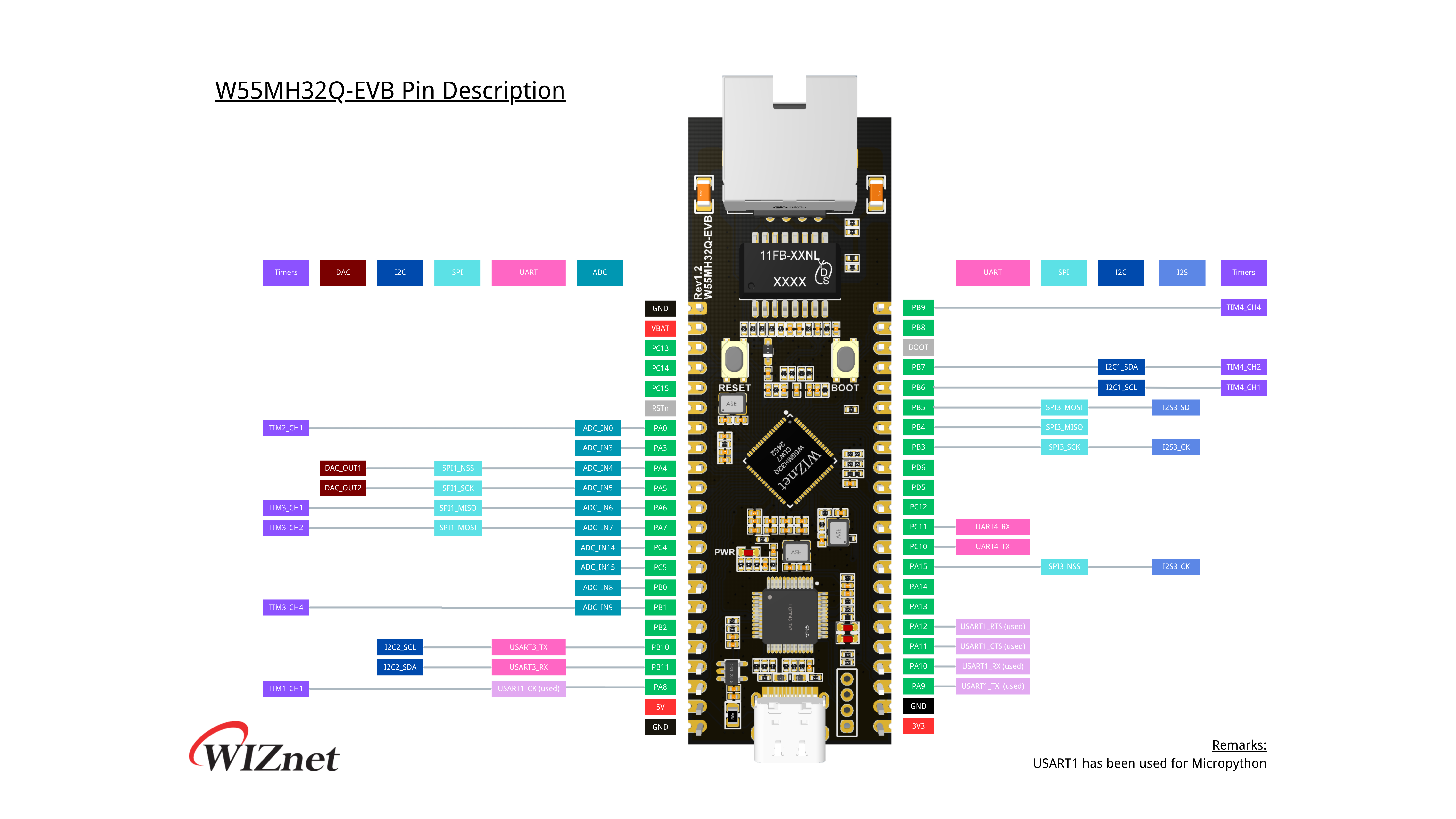
Pinout
The pinout diagram below shows the available pins on the W55MH32Q-EVB.
Frozen Modules
🧊 Click to expand – full list of frozen modules
General board control
The MicroPython REPL is on USART1 (PA9 = TX, PA10 = RX) at baudrate 115200. Tab-completion is useful to find out what methods an object has.
Basic setup
Hardware Connection
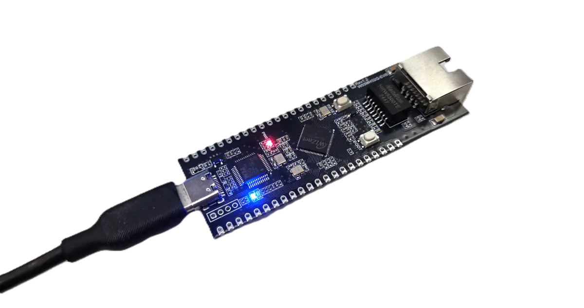
Use a USB Type‑C cable to connect the USB port on the W55MH32Q‑EVB to your PC.
This provides both power and serial communication for programming.
Firmware Installation
To install MicroPython firmware on the board:
Connect the USB port to your PC.
Windows will automatically detect a new drive named
WIZLINK.Drag and drop the
.hexfirmware file into theWIZLINKdrive window.
Note
The board will reboot automatically after the firmware is written.
Software Setup (Thonny)
Open Thonny IDE on your PC.
Select the correct COM port for your board.
Set the interpreter to MicroPython (generic).
Tip
If the COM port doesn’t appear, check that the USB cable is connected properly and the drivers are installed.
Networking
For testing the Ethernet feature of W55MH32Q-EVB, it is required to do the followings.
Connect the board and PC with an Ethernet cable.
Set the IP address of the board and PC in the same IP segment.
Run the script and ping the board IP.
See network.WIZNET5K
import network
import time
from machine import SPI, Pin

NET_IP   = "192.168.1.20"
NET_SN   = "255.255.255.0"
NET_GW   = "192.168.1.1"
NET_DNS  = "8.8.8.8"

spi = SPI(2, baudrate=8_000_000, polarity=0, phase=0)

cs  = Pin("PB12", Pin.OUT)
rst = Pin("PD9", Pin.OUT)
pwn = Pin("PE15", Pin.OUT, value =0)

nic = network.WIZNET5K(spi, cs, rst)

# Reset the WIZnet chip
nic.active(True)
nic.ifconfig((NET_IP, NET_SN, NET_GW, NET_DNS))

# Please use your PC to Ping "192.168.1.20"
Delay and timing
Use the time module:
import time

time.sleep(1)           # sleep for 1 second
time.sleep_ms(500)      # sleep for 500 milliseconds
time.sleep_us(10)       # sleep for 10 microseconds
start = time.ticks_ms() # get value of millisecond counter
delta = time.ticks_diff(time.ticks_ms(), start) # compute time difference
Pins and GPIO
See machine.Pin.
from machine import Pin

p_out = Pin('PD14', Pin.OUT)
p_out.high()
p_out.low()

p_in = Pin('PG6', Pin.IN)
p_in.value() # get value, 0 or 1
Timers
See machine.Timer.
from machine import Timer

tim = Timer(1, freq=1000)
tim.counter() # get counter value
tim.freq(0.5) # 0.5 Hz
tim.callback(lambda t: print("callback!!!"))
RTC (real time clock)
See machine.RTC
from machine import RTC

rtc = RTC()
rtc.datetime((2017, 8, 23, 0, 1, 12, 48, 0)) # set a specific date and
                                             # time, eg. 2017/8/23 1:12:48
                                             # the day-of-week value is ignored
rtc.datetime() # get date and time
ADC (analog to digital conversion)
See machine.Pin and machine.ADC.
from machine import Pin, ADC

adc = ADC(Pin('PA4'))
adc.read_u16() # read value, 0-4095
DAC (digital to analog conversion)
See machine.Pin and machine.DAC.
from machine import Pin, DAC

dac = DAC(Pin('PA4'))
dac.write(120) # output between 0 and 255
UART (serial bus)
See machine.UART.
from machine import UART

uart = UART(2, 115200)
uart.write('hello')
uart.read(5) # read up to 5 bytes
SPI bus
See machine.SPI.
from machine import SPI

spi = SPI(1, baudrate=200000, polarity=1, phase=0)
spi.write('hello')
spi.read(5) # receive 5 bytes on the bus
I2C bus
See machine.I2C.
from machine import I2C

i2c = I2C(1 , freq=400000)                 # create hardware I2c object

i2c.scan()                          # returns list of peripheral addresses
i2c.writeto(0x38, 'hello')          # write 5 bytes to peripheral with address 0x42
i2c.readfrom(0x38, 5)               # read 5 bytes from peripheral

i2c.readfrom_mem(0x38, 0x10, 2)     # read 2 bytes from peripheral 0x42, peripheral memory 0x10
i2c.writeto_mem(0x38, 0x10, 'xy')   # write 2 bytes to peripheral 0x42, peripheral memory 0x10