Sensor Module Guide
This page provides an overview of the modules available for the W55MH32L-EVB development board. Each module entry includes:
A brief description of the module’s purpose.
A link to the GitHub test code.
A demo GIF showing the module in action.
Use this guide to quickly reference how to use each module on your board.
DS18B20 (Temperature Sensor)
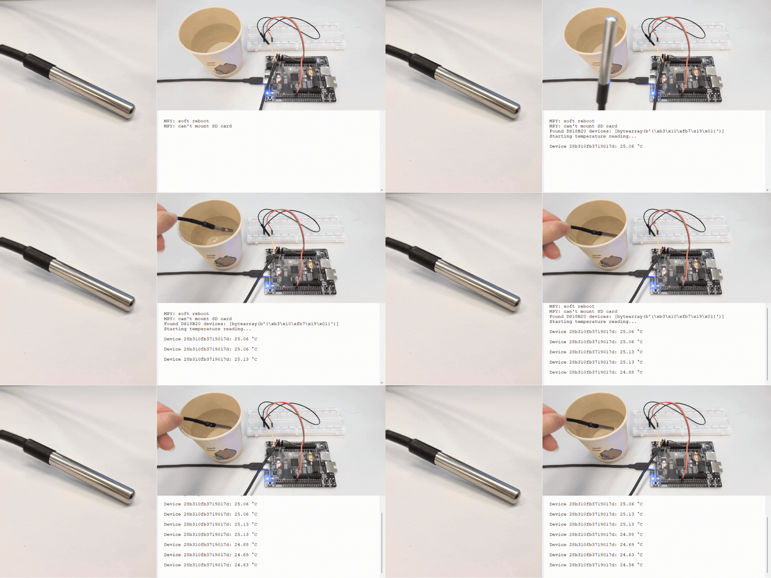
Description: The DS18B20 is a digital temperature sensor that uses the 1‑Wire protocol. It measures temperature with configurable resolution (9 to 12 bits) and returns readings in degrees Celsius.
Library Installation: This module requires the DS18B20 library to be downloaded to the board first.
Test Code: GitHub
Connection:
W55MH32 |
DS18B20 |
|---|---|
3V3 |
VDD |
GND |
GND |
PG4 (any GPIO) |
DQ |
Demo:
Water Depth Sensor
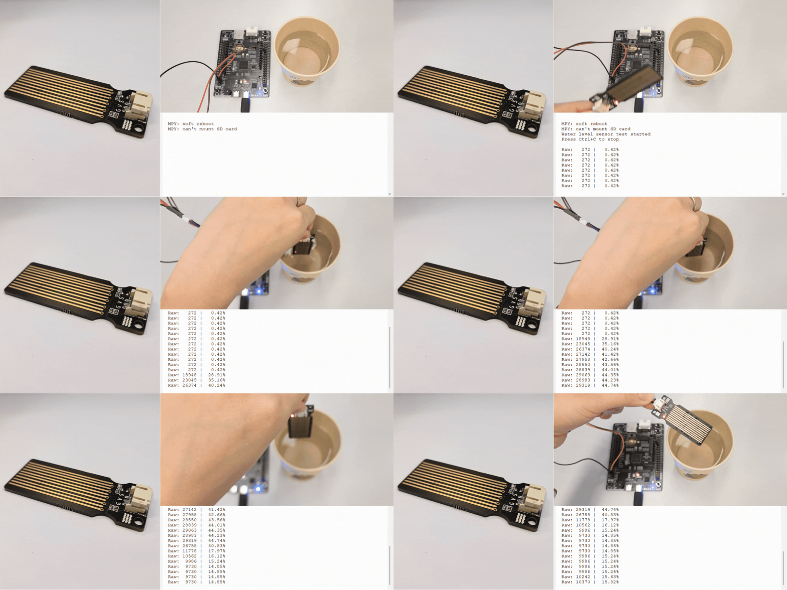
Description: The water depth sensor (also called a water level sensor) uses an analog voltage output that changes based on the water level. It outputs higher voltage (and higher ADC value) when submerged deeper.
Connection:
W55MH32 |
Water Depth Sensor |
|---|---|
3V3 (or 5V) |
VCC |
GND |
GND |
PA0 (ADC) |
Signal |
Test Code: GitHub
Demo:
TM1650 (4-Digit Display)
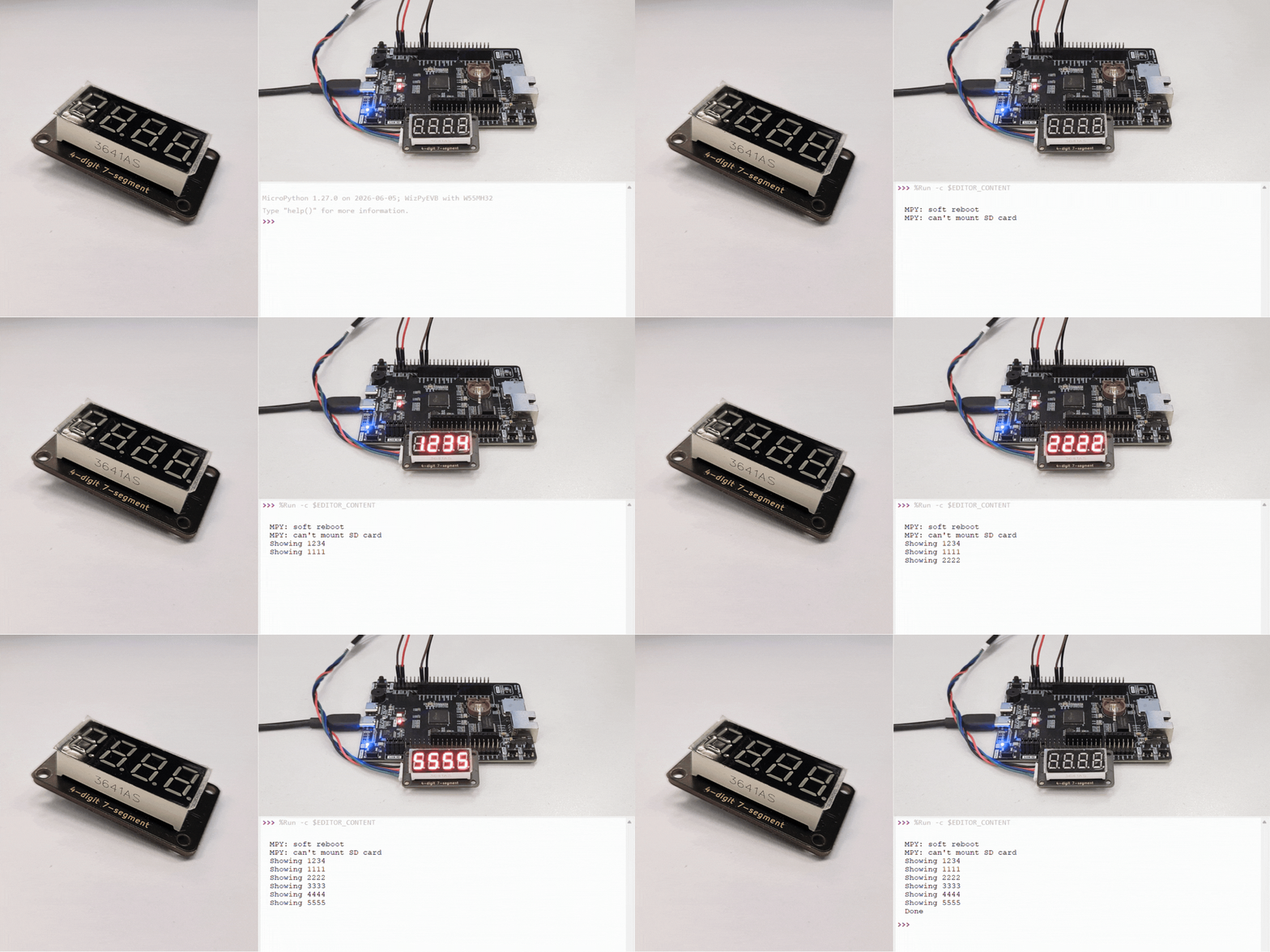
Description: The TM1650 is a driver IC for 4‑digit 7‑segment LED displays. It communicates via I2C and supports brightness control, individual digit control, and decimal points.
Library Installation: This module requires the TM1650 library to be downloaded to the board first.
Connection:
W55MH32 |
TM1650 Module |
|---|---|
3V3 |
VCC |
GND |
GND |
PB10 (SCL) |
SCL |
PB11 (SDA) |
SDA |
Test Code: GitHub
Demo:
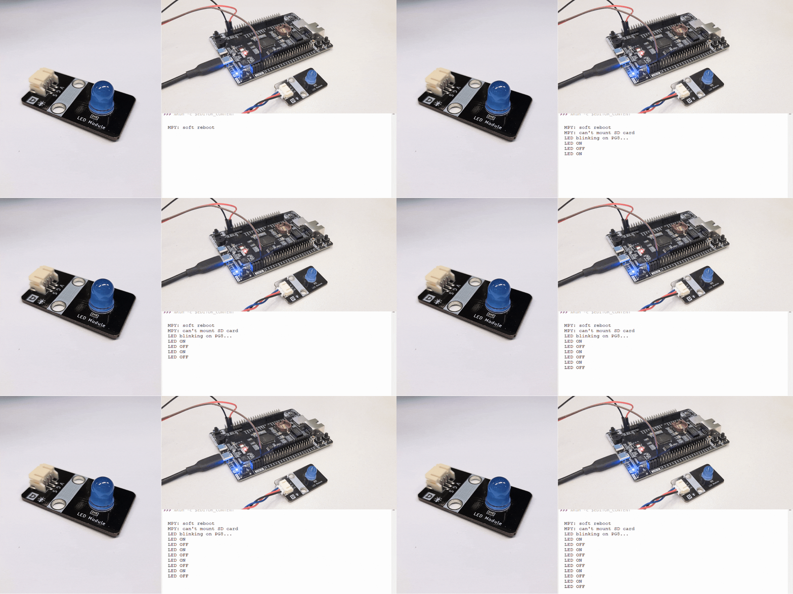
LED Module
Description: This is a 3‑pin LED module with onboard resistor and power LED. It can be easily connected to a GPIO pin for digital output control. The LED turns on when the signal pin is set HIGH or LOW.
Connection:
W55MH32 |
LED Module |
|---|---|
3V3 |
VCC |
GND |
GND |
PG8 |
Signal |
Test Code: GitHub
Demo:
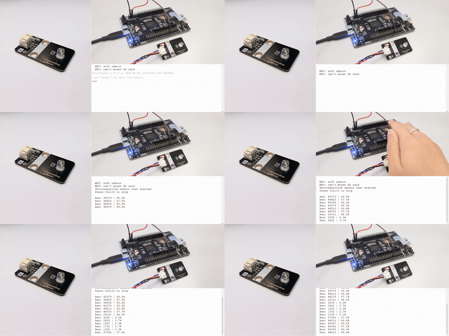
Photosensitive Sensor
Description: The photosensitive sensor module (also called a light sensor or photoresistor module) detects ambient light levels. It outputs an analog voltage that varies with light intensity – higher voltage (and higher ADC value) in bright light, lower voltage in darkness.
Connection:
W55MH32 |
Photosensitive Module |
|---|---|
3V3 |
VCC |
GND |
GND |
PA0 (ADC) |
Signal |
Test Code: GitHub
Demo:
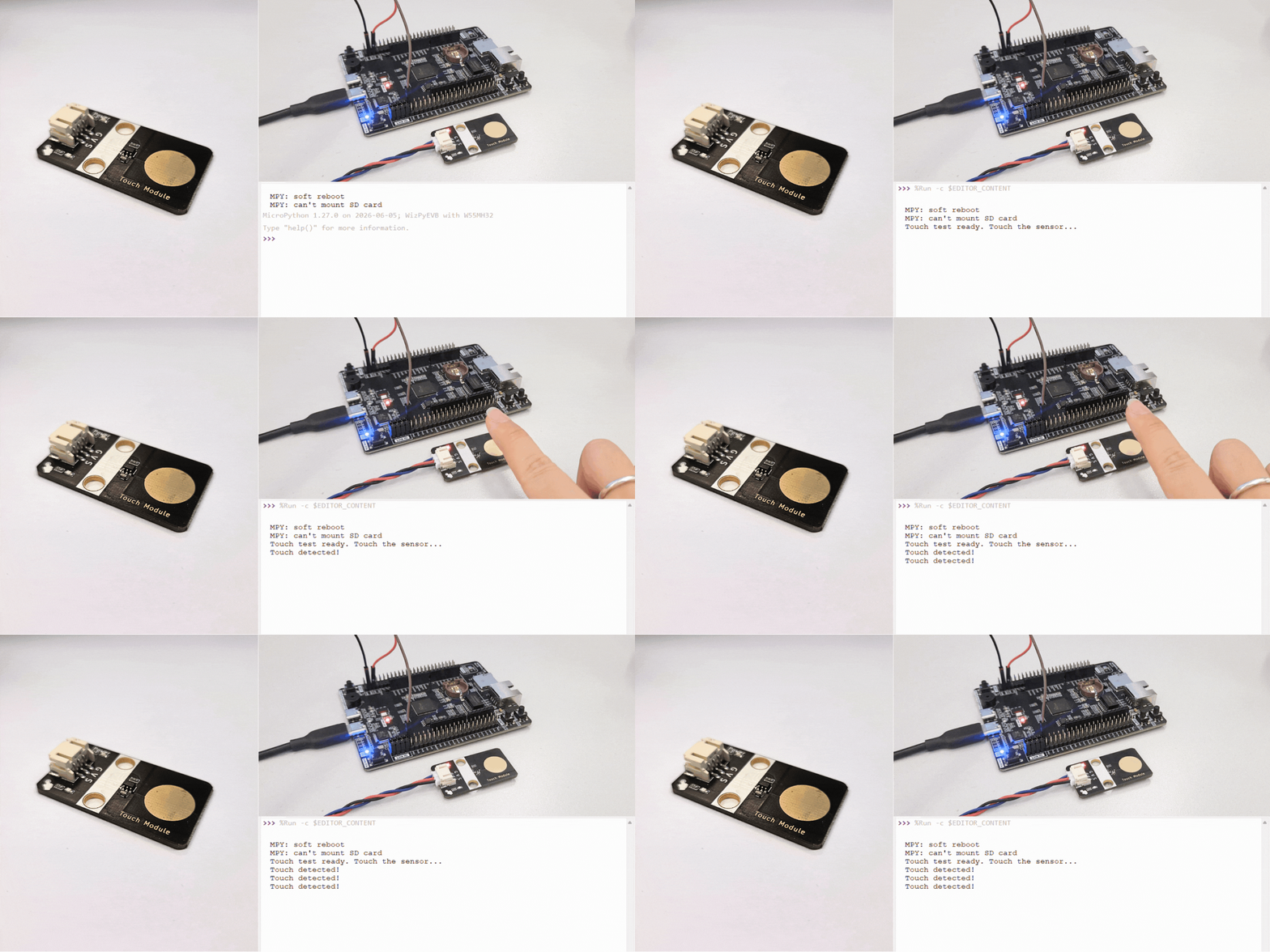
Touch Sensor
Description: The touch sensor module detects physical touch or proximity. It outputs a digital signal – HIGH when touched, LOW when not touched.
Connection:
W55MH32 |
Touch Module |
|---|---|
3V3 |
VCC |
GND |
GND |
PG8 |
Signal |
Test Code: GitHub
Demo:
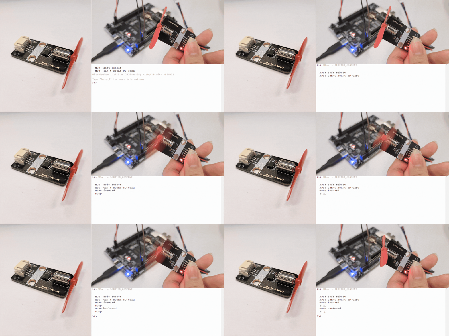
Motor Module
Description: The motor module using two GPIO pins to control the motor direction: one pin for forward, one pin for backward. The motor can be set to forward, reverse, stop, or brake.
Connection:
W55MH32 |
Motor Driver Module |
|---|---|
3V3 |
VCC |
GND |
GND |
PG8 |
IN1 (Forward) |
PG7 |
IN2 (Backward) |
Test Code: GitHub
Demo:
Flame Sensor
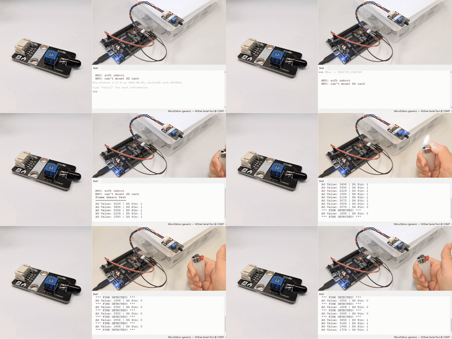
Description: The flame sensor module detects infrared (IR) radiation emitted by flames. It has both analog and digital outputs. The analog output provides a voltage proportional to flame intensity (higher value = less flame). The digital output is active LOW – it goes LOW when a flame is detected. A potentiometer on the module adjusts the digital threshold sensitivity.
Connection:
W55MH32 |
Flame Module |
|---|---|
3V3 |
VCC |
GND |
GND |
PA0 (ADC) |
AO (Analog Out) |
PG8 |
DO (Digital Out) |
Test Code: GitHub
Demo:
Passive Buzzer Module
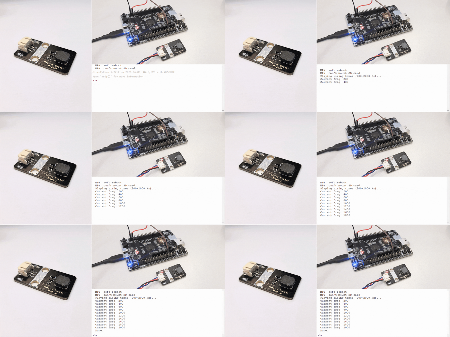
Description: The passive buzzer module generates tones of different frequencies using PWM (Pulse Width Modulation). Unlike an active buzzer which only produces a fixed frequency, a passive buzzer allows you to play melodies and varying tones by changing the PWM frequency.
Connection:
W55MH32 |
Passive Buzzer |
|---|---|
3V3 |
VCC |
GND |
GND |
PA0 (PWM) |
Signal |
Test Code: GitHub
Demo:
DHT22 (Temperature & Humidity Sensor)
Description: The DHT22 is a digital temperature and humidity sensor that uses a single‑wire protocol. It provides high accuracy readings: ±0.5°C for temperature and ±2‑5% for humidity.
Connection:
W55MH32 |
DHT22 Sensor |
|---|---|
3V3 |
VCC |
GND |
GND |
PG8 |
Signal |
Test Code: GitHub
Demo:
Bluetooth Module (BT04)
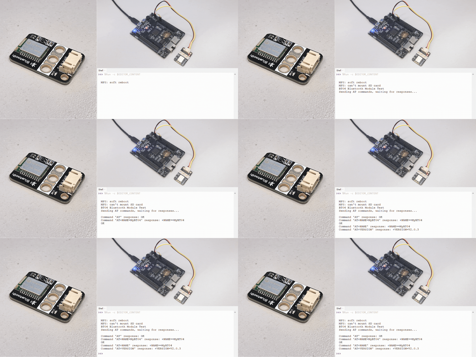
Description: The BT04 is a Bluetooth serial module that enables wireless communication between your board and other Bluetooth devices (like smartphones or PCs). It uses the UART interface for communication and supports AT commands for configuration (e.g., changing the device name, baud rate, or checking firmware version).
Connection:
W55MH32 |
BT04 Module |
|---|---|
3V3 |
VCC |
GND |
GND |
TX (UART3) |
RX (receive) |
RX (UART3) |
TX (transmit) |
Test Code: GitHub
Demo:
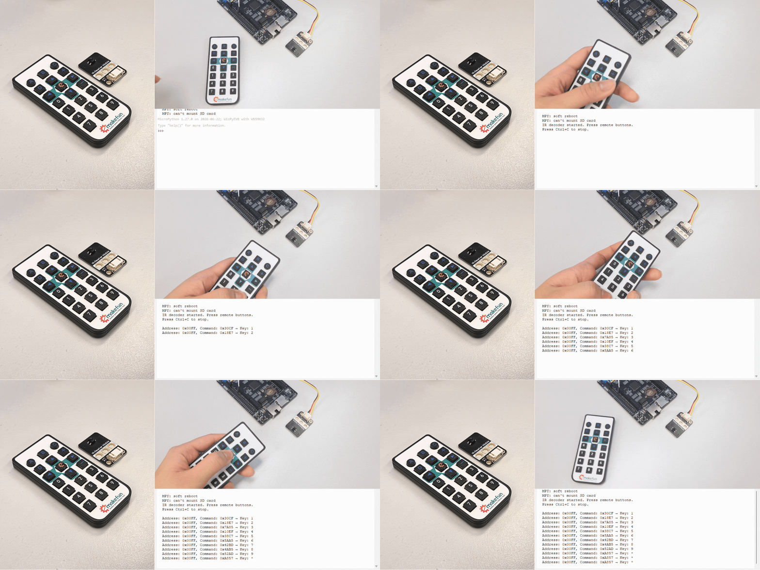
IR Module (Infrared Remote)
Description: The IR module (infrared receiver) detects signals from an infrared remote control. It uses a TSOP38238 or similar receiver that demodulates the 38kHz carrier signal. The module outputs a digital signal that can be decoded using the NEC protocol (commonly used by most IR remotes).
Connection:
W55MH32 |
IR Receiver |
|---|---|
3V3 |
VCC |
GND |
GND |
PG8 |
Signal (DO) |
Test Code: GitHub
Demo:
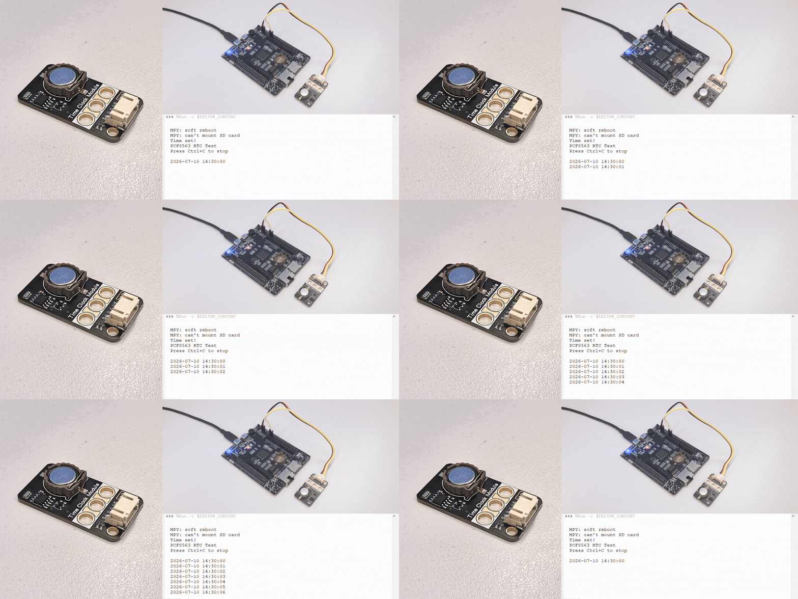
RTC Module (Real-Time Clock)
Description: The PCF8563 is a real-time clock (RTC) module that keeps track of the current date and time. It communicates via I2C and includes battery backup to maintain time when the main power is off.
Connection:
W55MH32 |
PCF8563 Module |
|---|---|
3V3 |
VCC |
GND |
GND |
PB10 (SCL) |
SCL |
PB11 (SDA) |
SDA |
Test Code: GitHub
Library Installation: This module requires the PCF8563 library to be downloaded to the board first.
Demo:
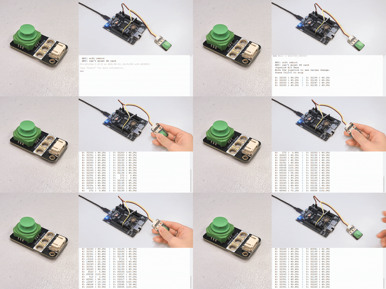
Joystick Module
Description: The joystick module is an analog thumbstick that provides X and Y axis position values. It typically includes a spring-loaded mechanism that returns to the center position when released. The module outputs two analog voltages (0–3.3V) that correspond to the X and Y positions.
Connection:
W55MH32 |
Joystick Module |
|---|---|
3V3 |
VCC |
GND |
GND |
PA0 (ADC) |
VRX (X-axis) |
PA1 (ADC) |
VRY (Y-axis) |
Test Code: GitHub
Demo:
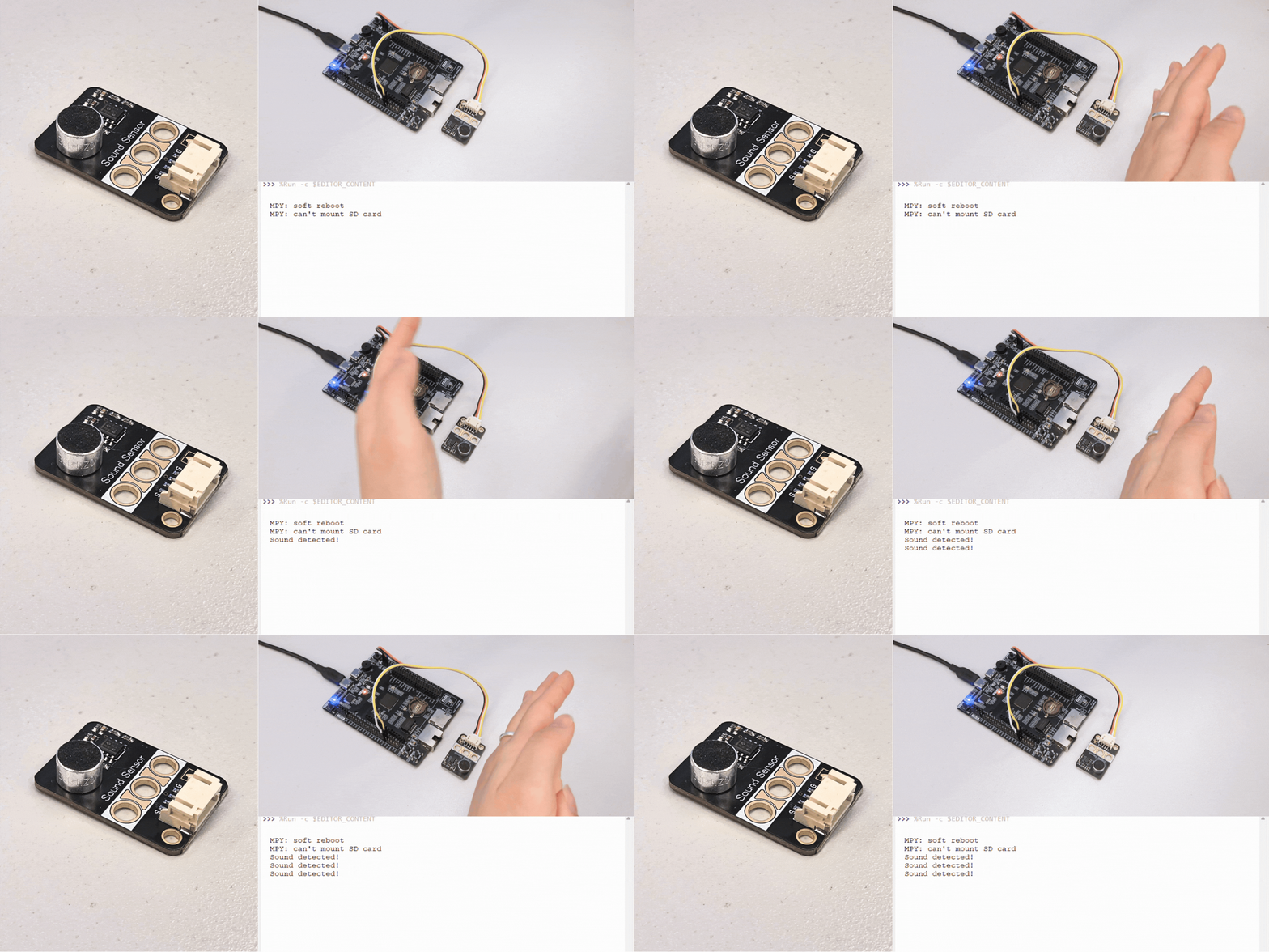
Sound Sensor
Description: The sound sensor module (also called a microphone or sound detector) detects ambient sound levels. It outputs an analog voltage that varies with sound intensity – higher voltage (and higher ADC value) when sound is detected.
Connection:
W55MH32 |
Sound Sensor |
|---|---|
3V3 |
VCC |
GND |
GND |
PA0 (ADC) |
Signal (AO) |
Test Code: GitHub
Demo:
Ultrasonic Sensor
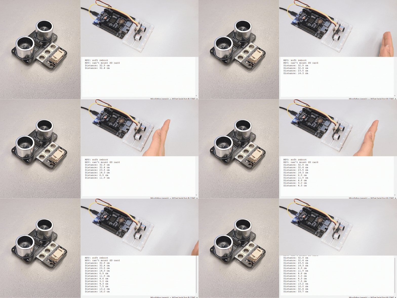
Description: The HC-SR04 ultrasonic sensor measures distance by emitting ultrasonic waves and measuring the time it takes for the echo to return. It provides precise distance measurements from 2cm to 4m. The sensor uses two pins: Trigger (output) and Echo (input).
Connection:
W55MH32 |
HC-SR04 Sensor |
|---|---|
3V3 |
VCC |
GND |
GND |
PG8 |
Trigger |
PG7 |
Echo |
Test Code: GitHub
Library Installation: This module requires the HCSR04 library to be downloaded to the board first.
Demo: