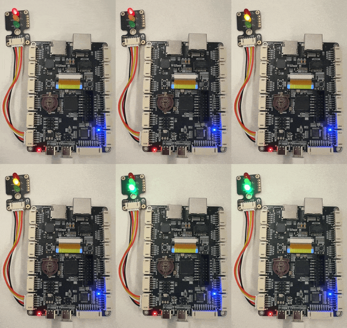
WIZM-LED3
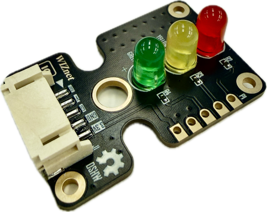
WIZM-LED3 is a 5-pin traffic light module that provides an intuitive visual signaling display by integrating discrete red, yellow, and green LEDs in a common anode configuration. Powered via dedicated 3V3 and GND pins, the active-low R, Y, and G control inputs allow independent sinking control over each colored indicator.
 Buy now
The WIZM-LED3 is an integrated visual indicator board featuring three standard through-hole LEDs (Red, Yellow, and Green) arranged in a traditional traffic-signal layout. Featuring a common anode topology with onboard current-limiting resistors, the LEDs operate via active-low logic where pulling a channel to GND turns the LED on. Dual header breakout options (standard 2.54mm pitch through-holes and a right-angle keyed connector) make it suitable for breadboard prototyping, rack status indication, and IoT controllers.
Features
Standard Traffic Light Configuration: Discrete Red, Yellow, and Green LEDs arranged vertically.
Common Anode (Active-Low): LEDs turn ON when driven LOW (
0) and turn OFF when driven HIGH (1).Onboard Current-Limiting Resistors: Plug-and-play operation directly with 3.3V logic levels without external resistors.
Dual Connection Options: Supports standard 2.54mm pitch pin headers alongside a keyed horizontal lock connector.
Mounting Holes: Four corner mounting holes plus a center pass-through hole for mounting onto panels or chassis.
Specifications
Parameter |
Value |
|---|---|
Model |
WIZM-LED3 |
Revision |
1.0 |
Operating Voltage (VCC) |
3.3V DC |
Control Logic |
Active-Low ( |
LED Colors |
Red, Yellow, Green |
Connector Pitch |
Standard 2.54mm (P1) / Keyed Horizontal (J1) |
Pin Count |
5 Pins ( |
Pinout & Hardware Overview
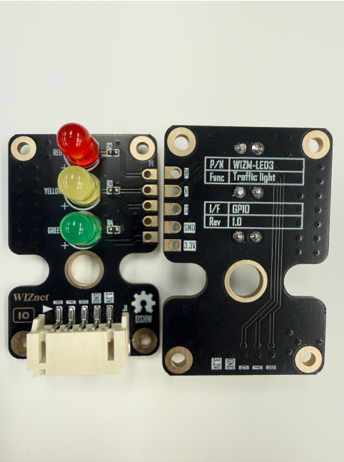
The module provides two parallel pin interfaces: a standard 5-pin 2.54mm pitch breakout (P1) and a 5-pin horizontal keyed connector (J1).
Pin |
Type |
Description |
|---|---|---|
R |
Input |
Control input for Red LED (Drive |
Y |
Input |
Control input for Yellow LED (Drive |
G |
Input |
Control input for Green LED (Drive |
GND |
Power |
Ground supply reference |
3.3V |
Power |
3.3V DC Power Supply |
Top View & Bottom View
Platforms Supported
MicroPython |
|---|
|

Getting Started
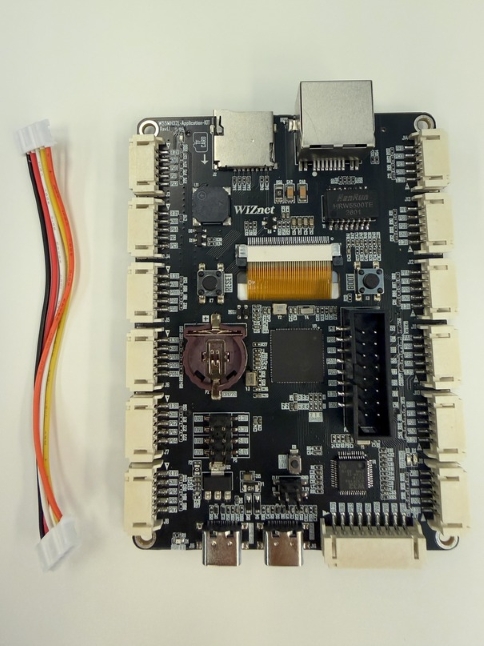
Materials Required (excluding traffic module)
W55MH32L-Application-KIT
5-pin female-female JST PH-Style Cable
USB Type-C Cable
Hardware Connection
Connect the WIZM-LED3 to the W55MH32L-Application-KIT with the JST PH-Style Cable:
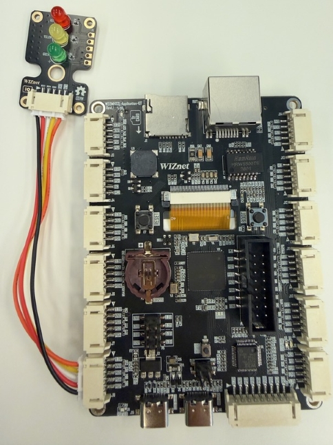
Then use a USB Type‑C cable to connect the WIZ‑LINK Port on the W55MH32L‑Application-KIT board to your PC
Sample Code Demo
Software
We will be using Thonny IDE to run the code.
Open Thonny IDE on your PC.
Select the correct COM port for your board.
Set the interpreter to MicroPython (generic).
Refer to the WIZnet documentation page for more detailed instructions at the “Basic Setup” section.
MicroPython
from machine import Pin
import time

# Initialize control pins as outputs.
# Configured for the carrier board's J8 JST connector
# Note: Update the pin assignments to match the pins connected to R, Y, and G on your setup.
red = Pin("PG5", Pin.OUT)
yellow = Pin("PG6", Pin.OUT)
green = Pin("PG7", Pin.OUT)

# Active-Low constants
LED_ON = 0
LED_OFF = 1

def turn_off_all():
    red.value(LED_OFF)
    yellow.value(LED_OFF)
    green.value(LED_OFF)

# Start with all LEDs off
turn_off_all()

while True:
    # Green Light
    turn_off_all()
    green.value(LED_ON)
    time.sleep(5)

    # Yellow Light
    turn_off_all()
    yellow.value(LED_ON)
    time.sleep(2)

    # Red Light
    turn_off_all()
    red.value(LED_ON)
    time.sleep(5)