WIZM-JOYSTICK
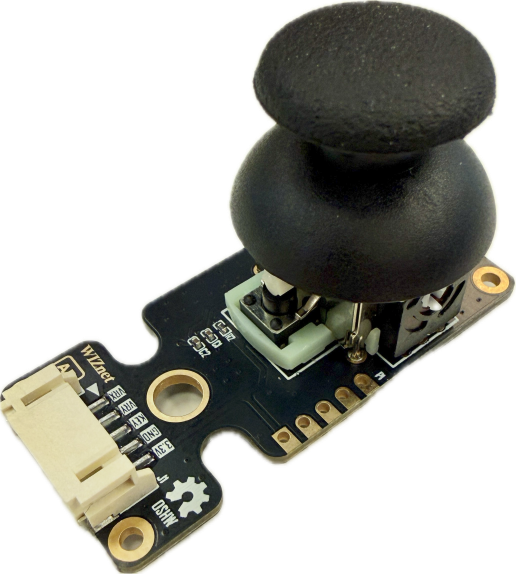
WIZM-JOYSTICK is a 2-axis analog rocker joystick module equipped with an integrated push-button switch. Operating at 3.3V, it provides proportional analog voltage outputs for X and Y coordinates along with a digital output for button clicks, enabling directional control and user input for embedded interfaces and robotics.
 Buy now
The WIZM-JOYSTICK is an analog input module based on two perpendicular $10\text{ k}\Omega$ potentiometers (X and Y axes) and an integrated momentary tactile push button. By converting mechanical stick deflection into proportional analog voltages ($0\text{ to }3.3\text{V}$), it provides smooth, multi-directional tracking alongside center-push selection. Dual connection options, a standard 2.54mm pitch header breakout alongside a keyed horizontal locking connector, make it straightforward to integrate into prototyping setups, gaming peripherals, pan-tilt gimbals, and IoT control panels.
Features
Dual-Axis Analog Output: Two orthogonal potentiometers provide smooth analog voltage readouts for X and Y position.
Integrated Push-Button (KEY): Center tactile switch activates when the joystick is pressed downward.
Spring Self-Centering: Returns automatically to the center position when released.
Dual Connection Options: Supports standard 2.54mm pitch through-hole headers alongside a keyed horizontal lock connector.
Mounting Holes: Corner mounting holes and center clearance cutouts for secure panel or chassis mounting.
Specifications
Parameter |
Value |
|---|---|
Model |
WIZM-JOYSTICK |
Revision |
1.0 |
Operating Voltage (VCC) |
3.3V DC |
Interface Type |
Analog (X/Y) + Digital (Push Button) |
Connector Pitch |
Standard 2.54mm (P1) / Keyed Horizontal (J1) |
Pin Count |
5 Pins ( |
Pinout & Hardware Overview
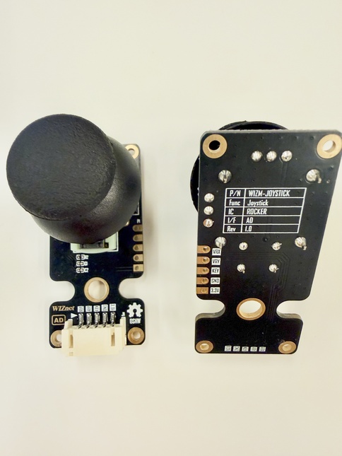
The module provides two parallel pin interfaces: a standard 5-pin 2.54mm pitch breakout (P1) and a 5-pin horizontal keyed connector (J1).
Pin |
Type |
Description |
|---|---|---|
VRX |
Input |
X-axis analog voltage output ($0\text{V} - 3.3\text{V}$) |
VRY |
Input |
Y-axis analog voltage output ($0\text{V} - 3.3\text{V}$) |
KEY |
Input |
Integrated push-button switch (Pushed to connect) |
GND |
Power |
Ground supply reference |
3.3V |
Power |
3.3V DC Power Supply |
Top View
Platforms Supported
MicroPython |
|---|
|
Getting Started
Materials Required (excluding joystick module)
W55MH32L-Application-KIT
5-pin female-female JST PH-Style Cable
USB Type-C Cable
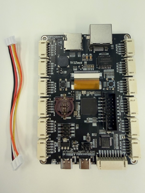
Hardware Connection
Connect the WIZM-JOYSTICK to an ADC-enabled connector (e.g., J3) on the W55MH32L-Application-KIT using the 5-pin JST cable.
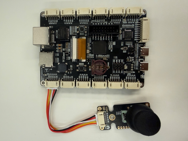
Then use a USB Type‑C cable to connect the WIZ‑LINK Port on the W55MH32L‑Application-KIT board to your PC
Sample Code Demo
Software
We will be using Thonny IDE to run the code.
Open Thonny IDE on your PC.
Select the correct COM port for your board.
Set the interpreter to MicroPython (generic).
Refer to the WIZnet documentation page for more detailed instructions at the “Basic Setup” section.
MicroPython
from machine import Pin, ADC
import time

# Configure ADC pins for X and Y axes
# Update pin names to match your board's ADC-capable pins
vrx = ADC(Pin("PA0"))
vry = ADC(Pin("PA1"))

# Configure digital input for the push button with an internal pull-up resistor
key = Pin("PA2", Pin.IN, Pin.PULL_UP)

print("Starting Joystick Read...")

while True:
    # Read 16-bit unsigned ADC values (0 - 65535)
    x_val = vrx.read_u16()
    y_val = vry.read_u16()

    # Read button state (0 = pressed when using pull-up)
    button_pressed = (key.value() == 0)

    print(f"X: {x_val:<5} | Y: {y_val:<5} | Pressed: {button_pressed}")
    time.sleep(0.1)
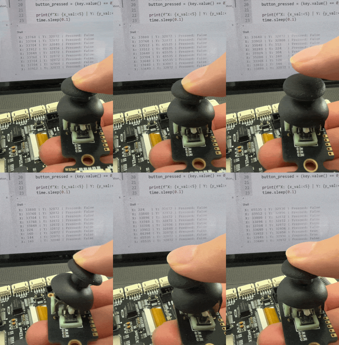
Moving the stick deflects the X and Y ADC readings up or down relative to their center resting values, and pressing down on the stick toggles “Pressed: True”.